Systems, methods and apparatus for specialized filtered back-projection reconstruction for digital tomosynthesis

a tomosynthesis and back-projection technology, applied in the field of digital imaging, can solve the problems of introducing reconstruction artifacts, unable to recover previously described loss of contrast for small structures, and the use of conventional shift and add algorithm suffers from considerable problems

Active Publication Date: 2007-12-18
GENERAL ELECTRIC CO
View PDF6 Cites 14 Cited by
  • Summary
  • Abstract
  • Description
  • Claims
  • Application Information

AI Technical Summary

Benefits of technology

[0013]In one aspect, a three-dimensional (3D) image of an object is constructed from a plurality of two-dimensional (2D) images of the object using a specialized filter. The specialized filter implements a linear ramp function, a windowing function, and / or a polynomial function. The 3D image is back-projected from the filtered two-dimensional images, yielding a 3D image that has improved visual distinction of overlapping anatomic structures and reduced blurring.

Problems solved by technology

However, this technique introduces reconstruction artifacts.
Also, the previously described loss in contrast for small structures is not recovered by the simple back-projection reconstruction technique.
Thus, the conventional shift and add algorithm suffers from considerable problems in this field of use.
ART tends to generate higher quality reconstructions than the “shift and add algorithm,” but is typically much more computationally complex than other techniques (e.g., the shift and add algorithm).
This computational cost and the associated delay until the final 3D image of the breast is available to the clinician can be prohibitive in practical clinical use.
Unfortunately, full 360 degree image acquisition is not practical for many applications including breast imaging, where design considerations limit the ability to rotate fully about the breast.
However, conventional X-ray imaging systems do not properly visually distinguish lung nodules in the X-ray image to the extent that 30% of nodules are medically diagnosed; 70% of lung nodules are not medically diagnosed.
The first reason is overlapping anatomic structures that constitute anatomic artifacts that cause anatomic imaging noise.
Lung nodules are less dense than these anatomic structures, making a lung nodule difficult to visually distinguish in the X-ray image.
If the view of the bird is obscured by the trees and leaves, the bird will be nearly impossible to visually identify in the forest.
Similarly, if the view of a lung nodule is obscured by ribs, the lung nodule will be nearly impossible to visually identify in the body.
The second reason for the inadequate imaging of X-ray imaging systems is that conventional X-ray images are inherently somewhat blurred.
The slight visual contrast may be very difficult to visually pick out in the image that is somewhat blurred.
But these algorithms are known to produce “streaking artifacts.” Conventional filtered back-projection is able to successfully enhance the contrast of SOIs of certain sizes, but suffers from artifacts caused by aliasing and the complexity to optimize the algorithm for all SOIs present in general X-ray radiography images.

Method used


Image

  • Systems, methods and apparatus for specialized filtered back-projection reconstruction for digital tomosynthesis
  • Systems, methods and apparatus for specialized filtered back-projection reconstruction for digital tomosynthesis
  • Systems, methods and apparatus for specialized filtered back-projection reconstruction for digital tomosynthesis

Examples


an embodiment

Methods of an Embodiment

[0036]In the previous section, a system level overview of the operation of an embodiment was described. In this section, the particular methods performed by an imaging system, a server and / or a client of such an embodiment are described by reference to a series of flowcharts. Describing the methods by reference to a flowchart enables one skilled in the art to develop such programs, firmware, or hardware, including such instructions to carry out the methods on suitable computerized system in which the processor of the system executes the instructions from computer-accessible media. Methods 100-300 and 700-900 are performed by a program executing on, or performed by firmware or hardware that is a part of, a computer, such as computer 1202 in FIG. 12.

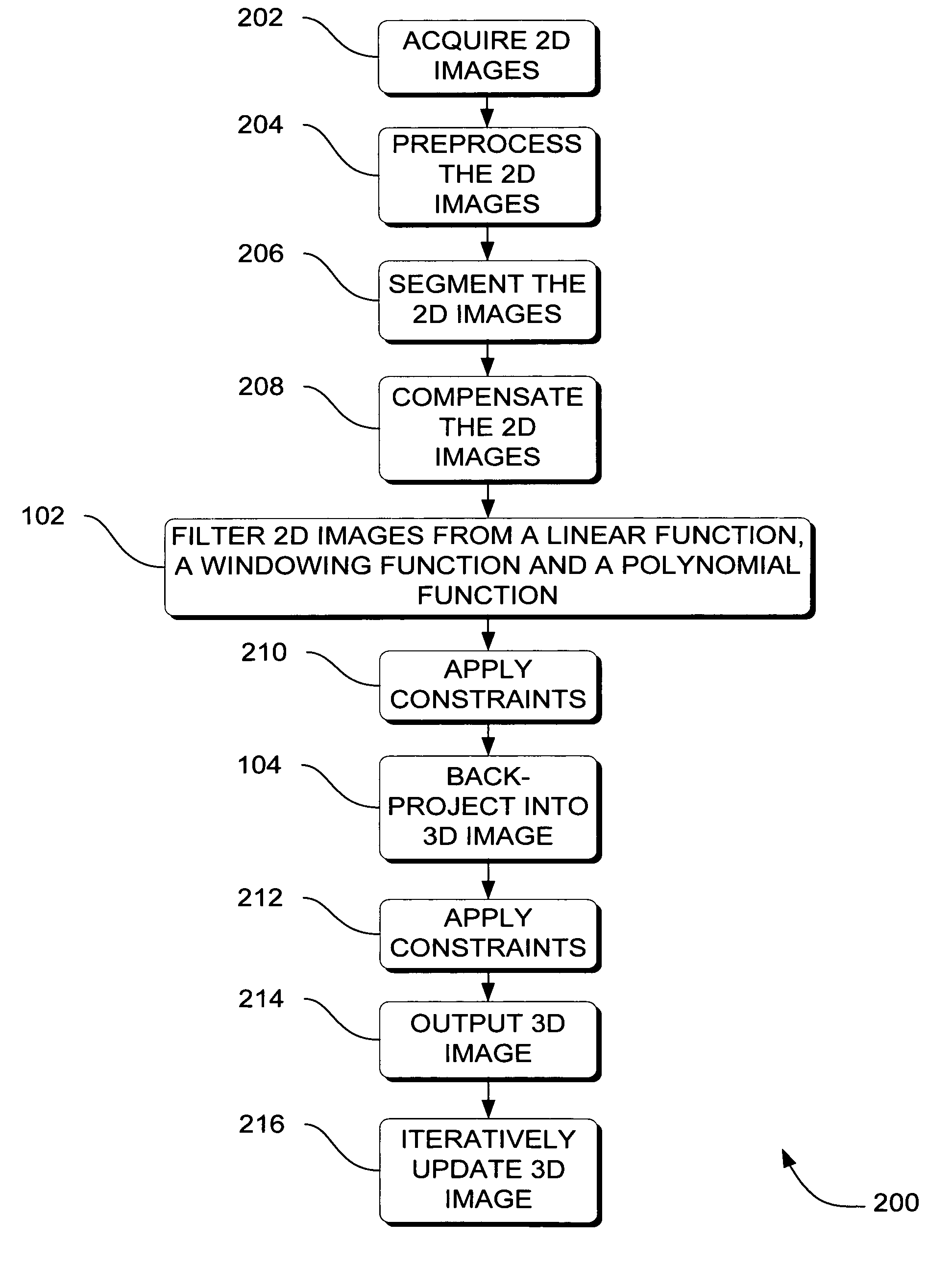
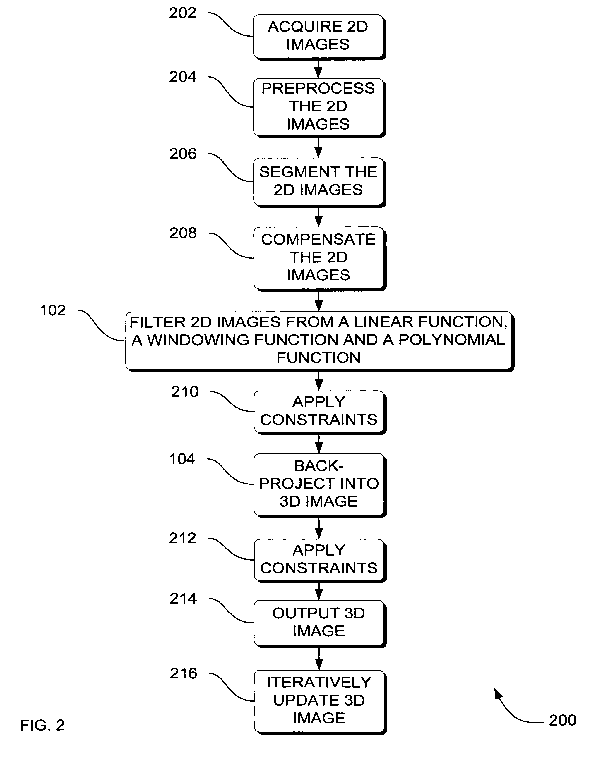
[0037]FIG. 2 is a flowchart of a method 200 of generating a 3D image from 2D images using specialized filter, performed by an imaging system according to an embodiment. In method 200, a plurality of 2D views of the ...


PUM


Abstract

Systems, methods and apparatus are provided through which in one aspect, a three-dimensional (3D) image of an object is constructed from a plurality of two-dimensional (2D) images of the object using a specialized filter. The specialized filter implements a linear ramp function, a windowing function, and / or a polynomial function. The 3D image is back-projected from the filtered two-dimensional images, yielding a 3D image that has improved visual distinction of overlapping anatomic structures and reduced blurring.

Description

RELATED APPLICATION[0001]This application is related to copending U.S. Publication No. 20030194049, filed Apr. 15, 2002 entitled “Generalized filtered back-projection reconstruction in digital tomosynthesis.”FIELD OF THE INVENTION[0002]This invention relates generally to digital imaging, and more particularly to reconstructing a three dimensional image using a tomosynthesis device.BACKGROUND OF THE INVENTION[0003]In X-ray tomosynthesis, a series of low dose X-ray images are acquired over a range of X-ray beam orientations relative to an imaged object. Digital tomosynthesis (DTS) is a limited angle imaging technique, which allows the reconstruction of tomographic planes on the basis of the information contained within the images acquired during one tomographic image acquisition. More specifically, DTS is reconstruction of three-dimensional (3D) images from two-dimensional (2D) projection images of an object.[0004]In DTS, one back-projection technique known as “simple back-projection”...

Claims


Application Information

Patent Timeline
Patent Type & Authority Patents(United States)
IPC IPC(8): G06K9/00
CPCG06T11/005G06T2211/436G06T2211/424
Inventor LI, BAOJUNMETZ, STEVEN W.SABOL, JOHN MICHAELAVINASH, GOPAL B.HSIEH, JIANG
Owner GENERAL ELECTRIC CO
Why Eureka
Try Eureka