Method for borehole measurement of formation properties

a technology of formation properties and measurement methods, applied in seismology for waterlogging, instruments, reradiation, etc., can solve problems such as unnecessarily reduced drilling rate, well blowout, and formation loss

Inactive Publication Date: 2007-12-18
EXXONMOBIL UPSTREAM RES CO
View PDF49 Cites 62 Cited by
  • Summary
  • Abstract
  • Description
  • Claims
  • Application Information

AI Technical Summary

Problems solved by technology

During the drilling of a petroleum well, accurate knowledge of formation pore pressure is necessary to ensure that formation fluids do not flow into the wellbore, which can potentially cause well blow-outs.
A problem with the use of drilling mud, however, is that if the pressure in the wellbore resulting from the mud's weight is too high, relative to the pore pressure, the drilling rate may be decreased unnecessarily.
In addition, if the pressure resulting from the mud's weight is excessively high compared to the pore pressure, that pressure may exceed the formation fraction pressure, potentially causing a loss of mud into the formation, and / or a well control problem.
This is often difficult, unfortunately, because accurate pre-drill knowledge of pore pressures is not always available, especially in areas with few previously drilled wells or where the geology is complex.
This 0.5 ppg wellbore pressure safety margin is in part required due to industry's present inability to accurately predict pore pressures in the various formations through which the drilling assembly will drill.
Pressure measurements from nearby offset wells can provide the most accurate pre-drill pressure information, but for remote locations these data are generally not available.
Pore pressure predictions from seismic data analysis typically suffer from large uncertainty however.
There are several contributing factors to this uncertainty, including the inherent uncertainty in the velocity models, the uncertainties in the variation of lithology compared with the data used to build the velocity-pore pressure empirical relationships, and the low vertical resolution of the seismic data.
In addition, large and significant pore pressure variation can occur over vertical intervals of rock much thinner than that which seismic data can resolve.
Unfortunately, there are also some important limitations with SWD.
For example, the resolution of analytic results from SWD data is generally limited by the relatively low seismic wave frequencies.
Second, poor SWD signals are received with polycrystalline diamond compact (PDC) bits, which are generally the preferred bits for drilling operations where high pore pressure is expected to be encountered.
Traditional roller-cone bits provide the best SWD signals but may compromise efficient drilling operations in many areas.
Third, drilling with downhole motors that rotate the bottomhole assembly while leaving the rest of the drillpipe non-rotating has become a preferred method in many areas, but that method also provides poor SWD signals.
Unfortunately, Barr's method is not feasible in most situations because of the need for the cable, which is disruptive to the drilling operation.
Beresford and Crowther do not disclose a method for determining formation properties however.
However, seismic signal velocities are poorly correlated with high-pressure zones, and seismic data resolution is far below that needed to make decisions during drilling.
A major disadvantage of VSP, however, is that the drill string must be removed for VSP measurements.

Method used


Image

  • Method for borehole measurement of formation properties
  • Method for borehole measurement of formation properties
  • Method for borehole measurement of formation properties

Examples


first embodiment

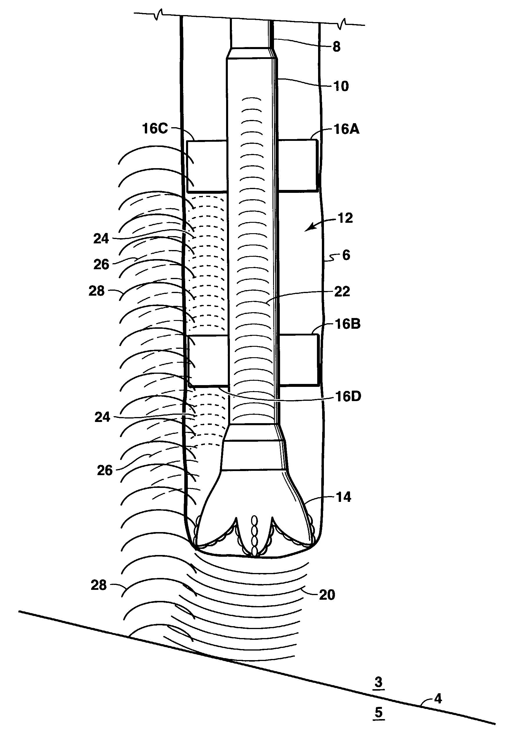
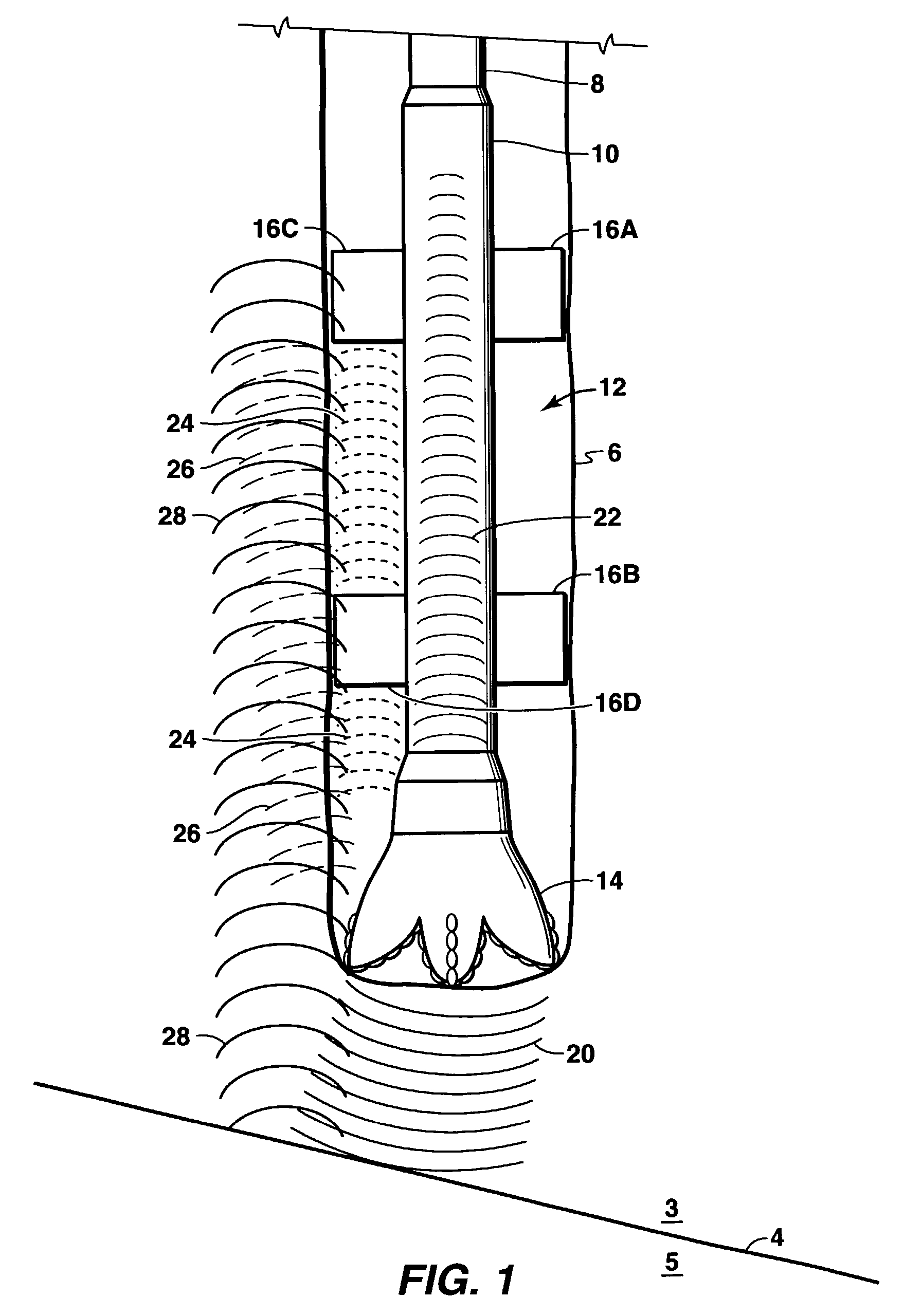
[0028]the present invention is depicted in FIG. 1. The measurement system of this embodiment includes a source for generating acoustic signals at or near the drill bit; a receiver array mounted on the BHA for detecting the signals generated by the source; hardware and software for signal processing, and a telemetry system for transmitting data to the drill rig.

[0029]The source for generating acoustic signals may be either passive or active. A passive source system will rely on the noise spectrum of the drill bit, which will typically involve large amplitude signals at frequencies up to about 20 kHz, to generate the source signal. The drill bit noise spectrum will generally have its highest amplitudes in the frequency of about 4 to about 6 kHz, and those amplitudes are typically far larger than the amplitudes of signals in the 10 to 100 Hz range which can be detected at the surface using seismic while drilling measurement techniques. The present invention teaches how to use these hig...

second embodiment

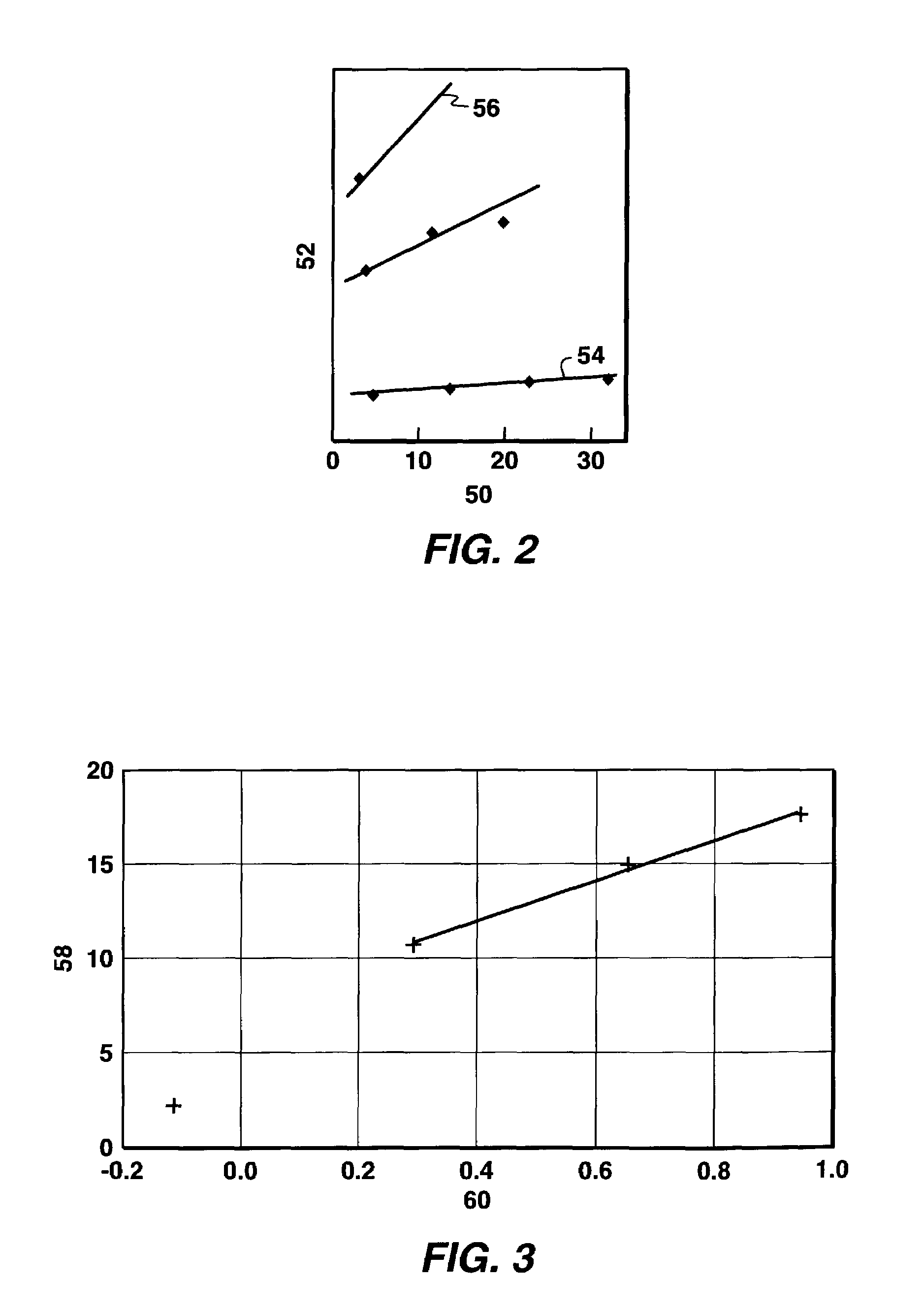
[0046]the method of the present invention allows estimation of pore pressure from the frequency-dependent change in velocity of the signals that propagate back to bottom hole assembly 12. Several mechanisms have been proposed to account for the frequency dependent wave propagation properties of fluid filled porous rocks, including the Biot slow wave mechanism and the squirt flow mechanism. In either case, both a frequency dependent velocity as well as a frequency dependent attenuation will result, and both will vary with the pore pressure. Thus, an alternate approach for estimating pore pressure ahead of the BHA is to measure the velocity of the waves traveling through the formation and reflected back to the receivers on the bottom hole assembly as a function of frequency. Following practices which are understood in the geophysical industry, wave propagation velocities as a function of frequency can be determined from the time of arrival of the wave front at the receiver and the emp...

third embodiment

[0047]the method of the present invention allows the estimation of pore pressure from the calculation of the ratio of the measured compressional wave velocity (Vp) to the shear wave velocity (Vs). Measured ultrasonic frequency data suggests that the ratio Vp / Vs increases by approximately 10% as the pore pressure increases from a negligible value up to the confining pressure. See for example, Christensen and Wang, 1985, “The Influence of Pore Pressure and Confining Pressure on Dynamic Elastic Properties of Berea Sandstone,” Geophysics, vol. 50, No. 2, pp. 207–213. The Christensen and Wang data relate changes in the confining and pore pressures in a formation to the Poisson's ratio. It will be understood to those skilled in the art that Poisson's ratio can be directly calculated from the ratio of the compressional wave velocity to the shear wave velocity. Thus, in this embodiment of the method of the present invention, pore pressure may be estimated by analysis of the compressional an...


PUM


Abstract

The present invention is a method of estimating formation properties by analyzing acoustic waves that are emitted from and received by a bottom hole assembly. A bottom hole assembly may be deployed in a borehole to estimate formation properties. From the bottom hole assembly, a source signal may be emitted and at least one signal may be received by one or more receivers in the bottom hole assembly. Analysis of the frequency dependent characteristics of the received signal allows the estimation of the formation properties of interest, including pore pressure. The formation properties of interest may be used to monitor a wellbore pressure safety margin and to optimize drilling and weight.

Description

[0001]This application is a continuation-in-part of U.S. application Ser. No. 09 / 686,735 filed Oct. 10, 2000, now abandoned, and of co-pending U.S. application Ser. No. 09 / 973,529 filed Oct. 9, 2001 now abandoned.FIELD OF THE INVENTION[0002]The present invention is a method of estimating a formation's properties, more specifically pore pressure, using a bottom hole assembly which has not yet penetrated the formation.BACKGROUND OF THE INVENTION[0003]The pore-fluid pressure of a rock formation, which is also referred to as simply the pore pressure, is measured relative to normal pressure at the depth of the formation, in other words relative to the hydrostatic pressure of a column of water at that depth. During the drilling of a petroleum well, accurate knowledge of formation pore pressure is necessary to ensure that formation fluids do not flow into the wellbore, which can potentially cause well blow-outs. A drilling fluid, usually referred to as drilling mud or simply mud, with desi...

Claims


Application Information

Patent Timeline
Patent Type & Authority Patents(United States)
IPC IPC(8): G01V1/40G06G7/48G01V1/50
CPCG01V1/50
Inventor ZHOU, MINYAOTHOMANN, HANSKELLER, STUART RONALD
Owner EXXONMOBIL UPSTREAM RES CO
Why Eureka
Try Eureka