Substrate support system

a support system and substrate technology, applied in the direction of work holders, metal-working machine components, manufacturing tools, etc., can solve the problems of difficult to hold the pcb flat and level under the stencil during the application of solder paste and then during the placement of components, and the approach is not practical for manufactures or subcontractors producing a very large number of pcb configurations. to achieve the effect of preventing flexing

Active Publication Date: 2007-12-25
PRODN SOLUTIONS
View PDF4 Cites 25 Cited by
  • Summary
  • Abstract
  • Description
  • Claims
  • Application Information

AI Technical Summary

Benefits of technology

[0020]The present invention provides an improved method for clamping spring loaded pins that support substrates, such as printed circuit boards, which have even profiles, and uneven profiles due to components being installed on one side, during manufacturing operations to the opposite side of the substrate. Typically, the substrate needs support to prevent flexing during manufacturing operations such as solder paste printing, pick-and-place operations, and any other operation where it is desirable to keep the substrate from flexing.

Problems solved by technology

However, there are a number of problems associated with installing parts on the second side after components have been mounted on the first side.
This problem is most acute when solder paste is to be printed on the second side.
Holding the PCB flat and level under a paste application stencil during solder paste application and then during component placement is very difficult.
This approach is not practical for manufactures or subcontractors producing a limited quantity of a very great number of PCB configurations, each requiring its own “hogged-out” support plate.
While effective where a large number of identical boards are to be manufactured, these methods are not cost effective where only a few boards are to be made or where custom boards are being manufactured.
While these supports are generally effective for their intended purposes, they are overly complex, and do not always provide positive support across the supported object.
Since the pistons are not lockable to match a particular PCB, each succeeding board must be pressed down against the pistons, risking damage.
Further, the system is not readily useful in installing components on the back of the board, since the pistons continue to press upwardly so that the board may not lie truly flat and may move during back-side component installation.
While this method is simple, it will eventually permanently deform the middle plate at the point where force is applied.
This method is not as robust as it could be, in that the anchor points of the cam wear easily because the plates are very thin (typically 0.048″ thick) and made from aluminum.

Method used


Image

  • Substrate support system
  • Substrate support system
  • Substrate support system

Examples


Embodiment Construction

[0034]Persons of ordinary skill in the art will realize that the following disclosure is illustrative only and not in any way limiting. Other embodiments of the invention will readily suggest themselves to such skilled persons having the benefit of this disclosure.

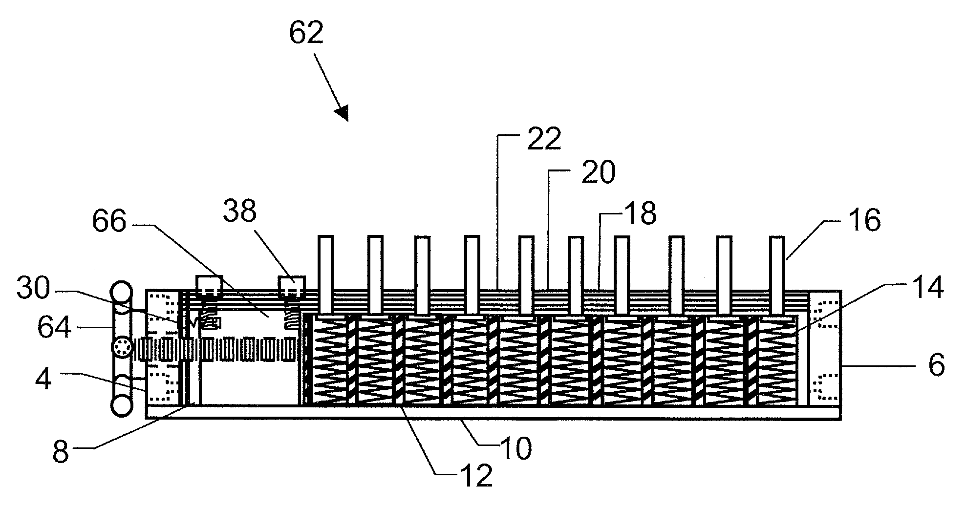
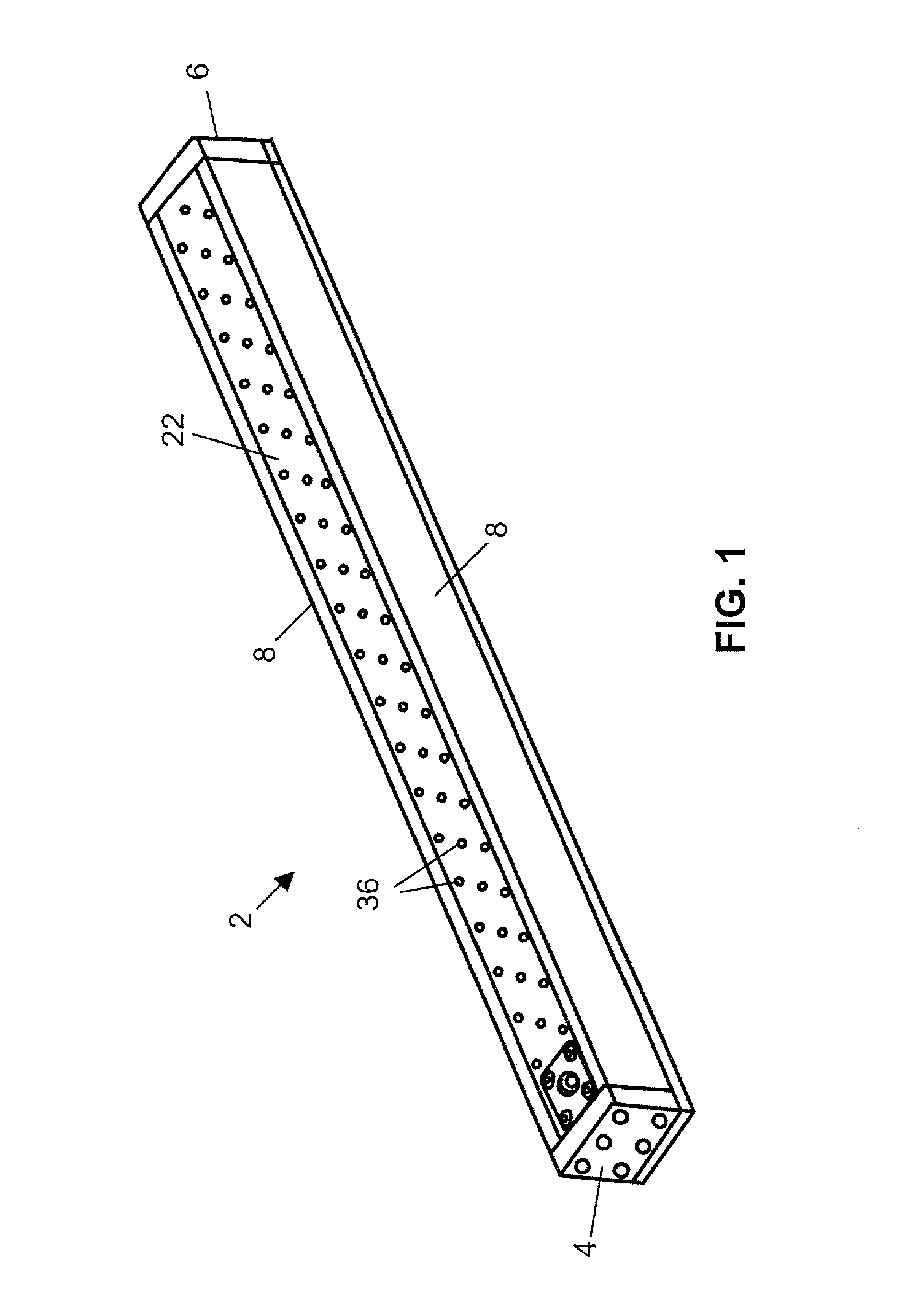
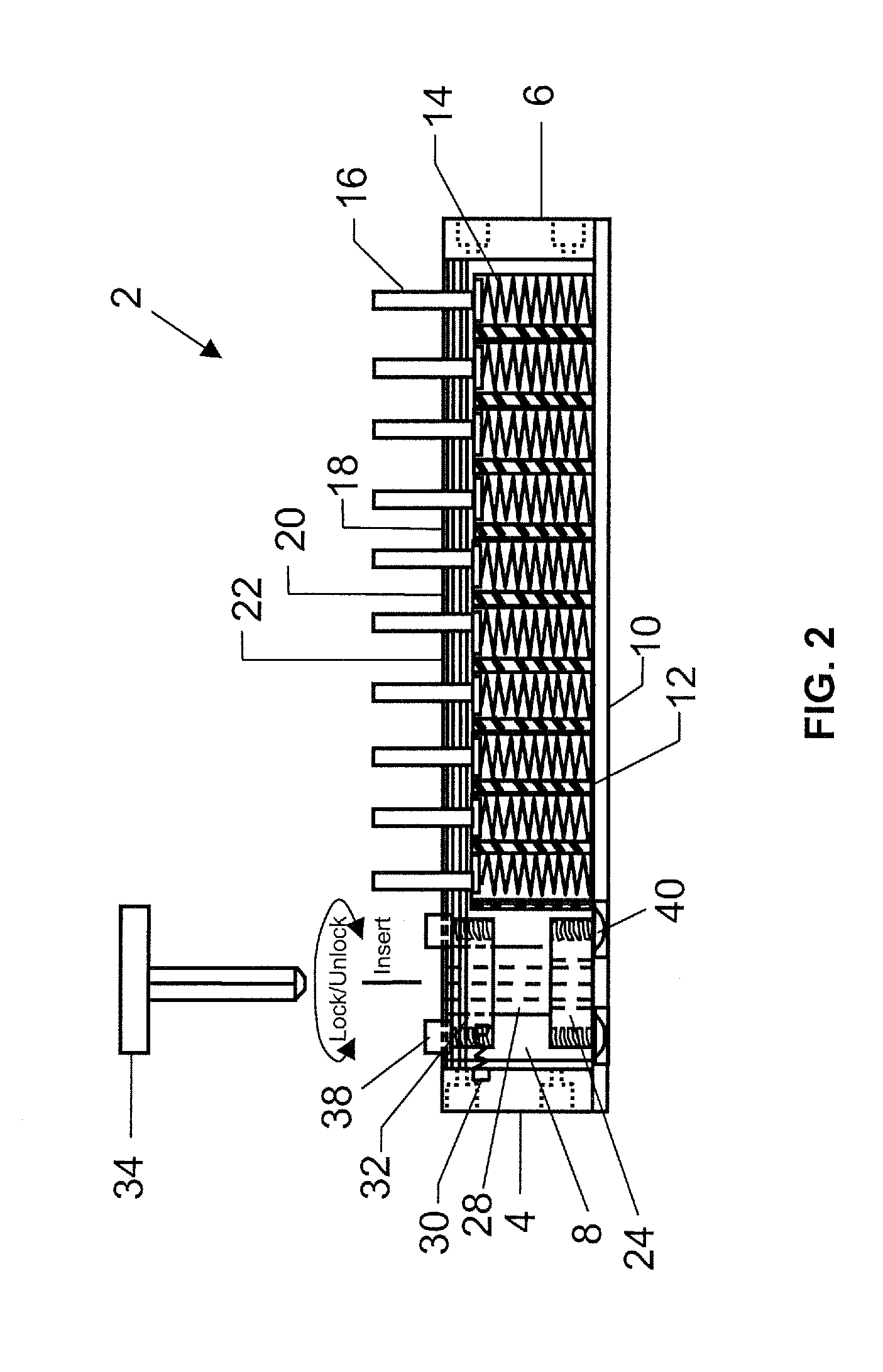
[0035]FIGS. 4-5 illustrate a substrate support system 42 for supporting PCB's having components installed on one surface while installing other components on the opposite surface. If desired, a PCB with no installed components may also be supported.

[0036]Substrate support system 42 comprises elastically compressible members 14 positioned on base plate 10. Base plate 10 is configured to receive and maintain the lateral position of members 14 in a plurality of recess positions. These recess positions can be achieved in a variety of ways, such as disposing insert plates 12 between members 14, as seen in FIG. 5, and / or by forming simple recesses in base plate 10. In a preferred embodiment, insert plates 12 are formed from plas...


PUM


Abstract

An improved substrate support system for clamping spring loaded pins that support substrates, such as printed circuit boards, which have even profiles, and uneven profiles due to components being installed on one side during manufacturing operations to the opposite side of the substrate. The substrate support system can utilize a cam lever, a knob, or a draw latch to move a clamping plate between an aligned position and a clamping position.

Description

FIELD OF THE INVENTION[0001]The present invention relates to an apparatus for supporting a printed circuit board or other substrate typically having components mounted on one side during installation of other components on the opposite side.BACKGROUND OF THE INVENTION[0002]Printed circuit boards (PCB) have long been used as the base for sophisticated electronic systems. An electrically insulating sheet, originally phenolic impregnated fabrics and now generally fiberglass reinforced resins, is coated with copper cladding and has appropriate patterns etched into the cladding. In years past, most electronic components had wire leads that extended through holes drilled into the cladding pattern and filled with solder to make the required connections. More recently, surface bonding of relatively short leads to the cladding has become common, allowing for high-speed robotic placement of components.[0003]Today, electronic devices are increasingly miniaturized and it has become desirable to...

Claims


Application Information

Patent Timeline
Patent Type & Authority Patents(United States)
IPC IPC(8): B23Q3/00
CPCH05K13/0069
Inventor FARLOW, DOUGLAS T.GORDON, THOMAS A.
Owner PRODN SOLUTIONS
Why Eureka
Try Eureka