
Method for manufacturing a scale, a scale manufactured according to the method and a position measuring device

a manufacturing method and a technology of a position measuring device, applied in the direction of measurement devices, instruments, optics, etc., can solve the problems of affecting the quality of the finished product, the inability to produce satisfactorily fine and sharp graduations using conventional materials, and the physical limits of photolithography methods with regard to the fineness of the structure, etc., to achieve good optical properties and fine graduations

Inactive Publication Date: 2007-12-25
DR JOHANNES HEIDENHAIN GMBH
View PDF23 Cites 6 Cited by
  • Summary
  • Abstract
  • Description
  • Claims
  • Application Information

AI Technical Summary

Benefits of technology

This approach enables the manufacturing of incident-light phase gratings with fine graduations and high diffraction efficiency, allowing for precise position measurement, overcoming the limitations of conventional materials and photolithography methods.

Problems solved by technology

However, there are physical limits to the photolithography methods with regard to the fineness of the structures to be manufactured.
These unwanted diffraction effects are minimized in the manufacture of such scales designed as incident-light phase gratings by the electron-beam lithography method, but a satisfactorily fine and sharp graduation cannot be produced using conventional materials such as gold for the reflective layers.
However, limits are encountered with respect to the fineness of graduations that are manufacturable when gold and chromium are used as the bottom reflector layer in combination with electron-beam lithography.
The reason for this is the backscatter electrons which impinge on the photoresist from the rear in structuring, so that the fine graduation quality manufactured in this manner may not be adequate.

Method used


Image

  • Method for manufacturing a scale, a scale manufactured according to the method and a position measuring device
  • Method for manufacturing a scale, a scale manufactured according to the method and a position measuring device
  • Method for manufacturing a scale, a scale manufactured according to the method and a position measuring device

Examples


Embodiment Construction

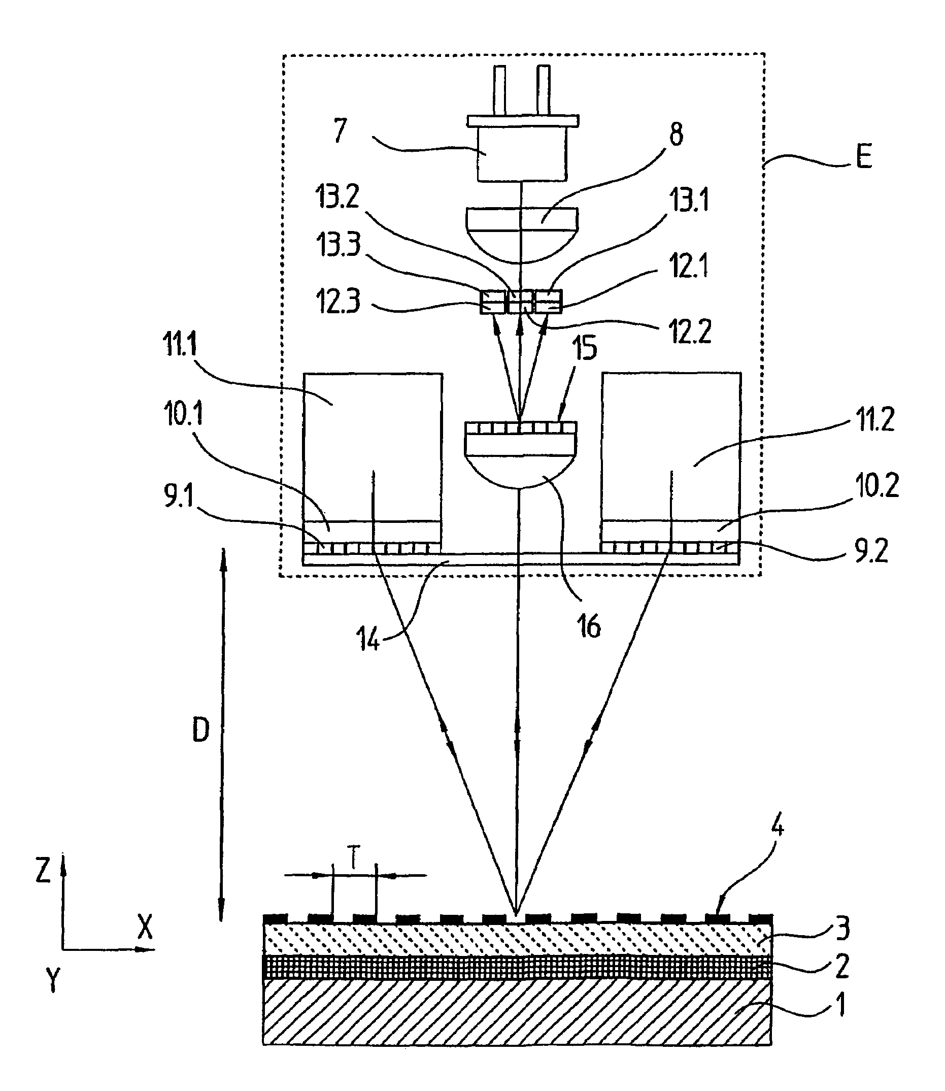
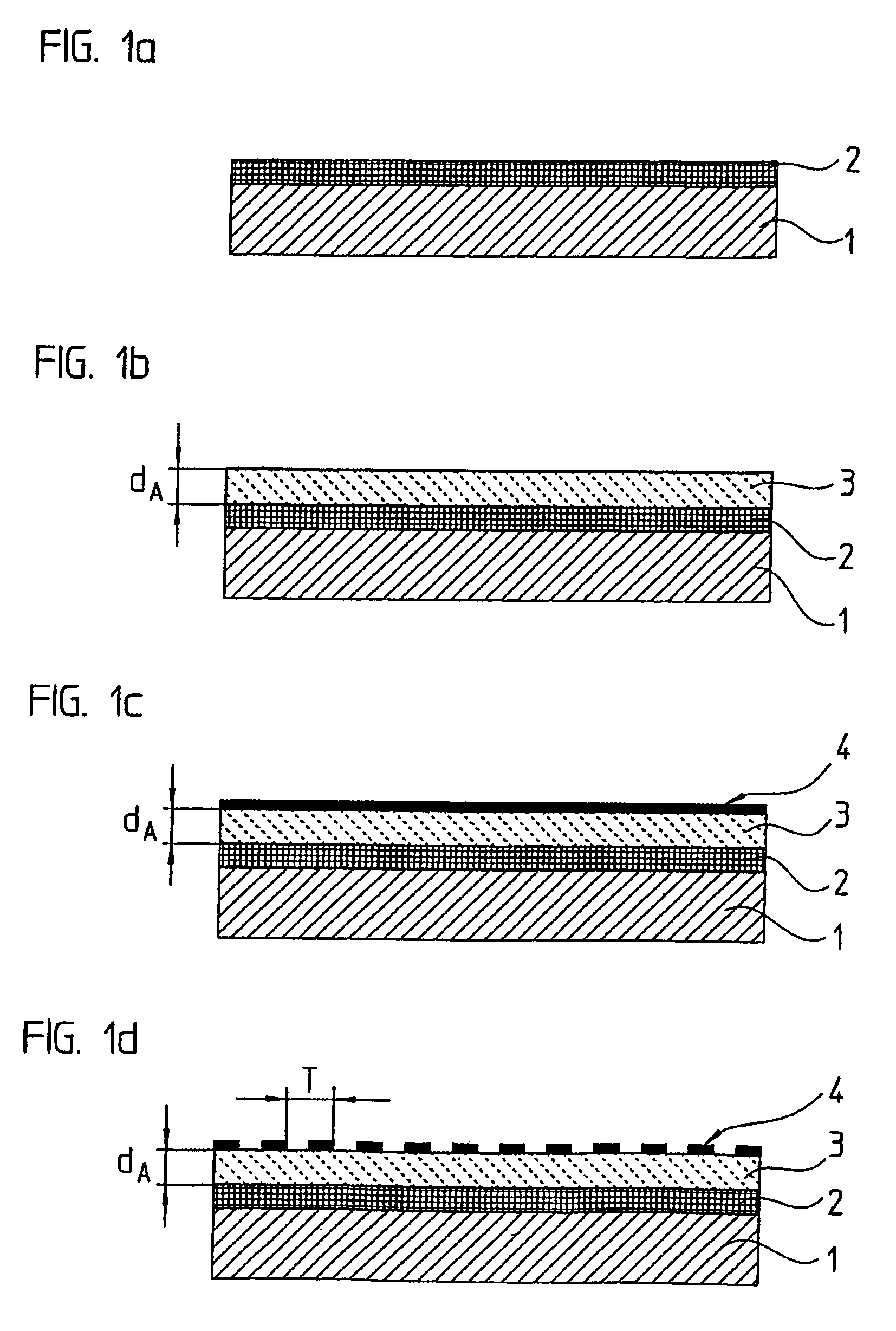
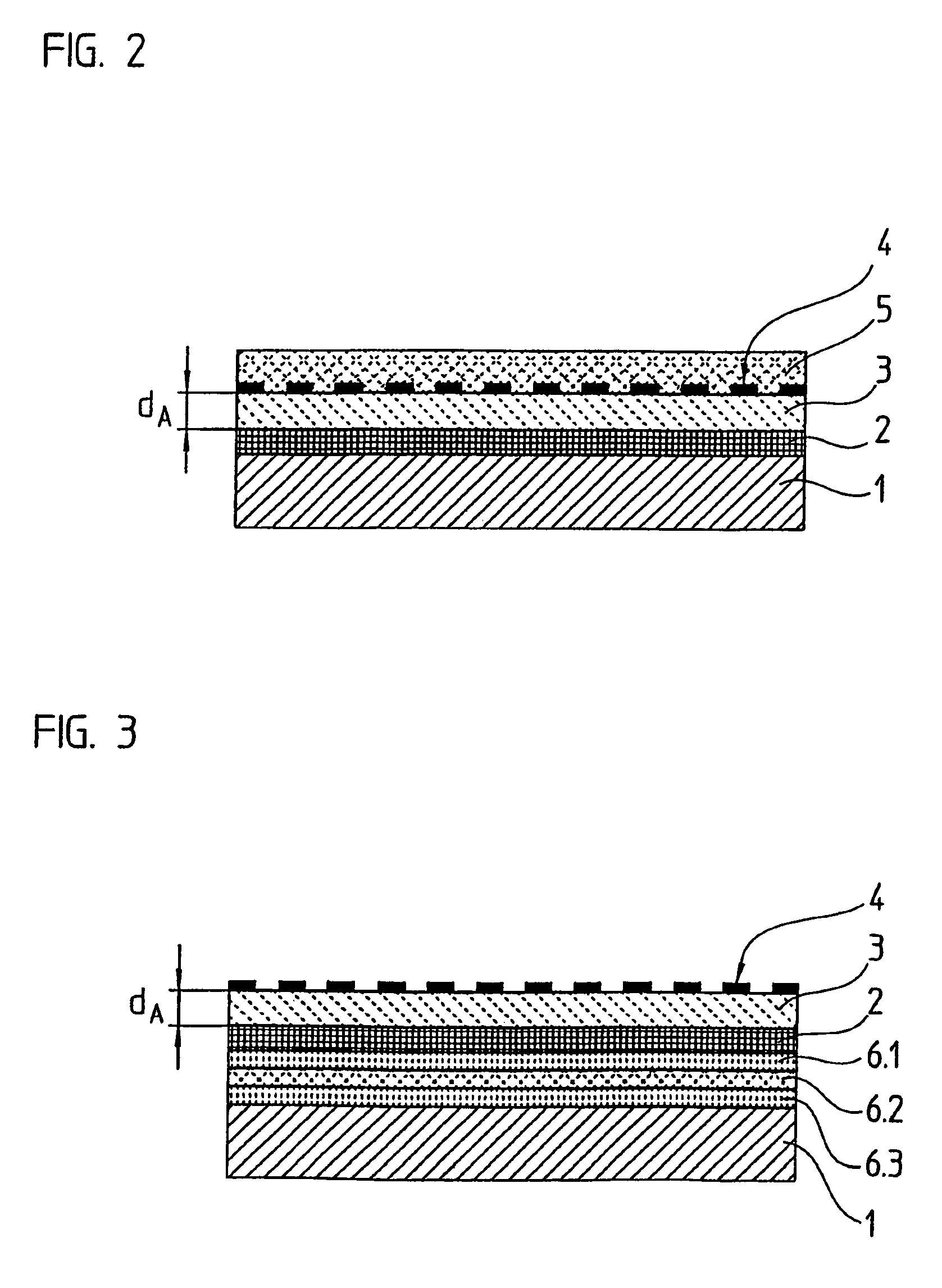
[0026]According to FIG. 1a, first a 100 nm thick bottom reflector layer 2 is applied by vacuum sputtering to a carrier substrate of aged Zerodur. Bottom reflector layer 2 is applied over the entire surface, i.e., without periodic interruptions, in the area of its surface which is illuminable during operation.

[0027]The material for carrier substrate 1 is selected to have the greatest possible stability with respect to both mechanical and thermal stresses. In particular, aged Zerodur which has a thermal expansion coefficient of almost zero may be particularly suitable for this purpose. However, quartz glass, other optical glasses, steel such as Invar and ceramics or silicon may also be considered as alternative carrier substrate materials. Stability with respect to possible temperature-induced changes in volume or length may be important in particular when the incident-light phase grating according to an example embodiment of the present invention is used in position measuring devices...


PUM


Abstract

In a method for producing a scale in the form of a phase grating, the scale itself, and a position measuring device including the scale, the scale includes two reflection layers located at a distance from one another on either side of a spacer layer. The production of the scale includes the following steps: provision of a first reflection layer, which is unbroken over its entire surface and fulfils the relationship A=R / η≧3, where R represents the degree of reflection and η represents the backscatter coefficient for electrons; application of the spacer layer to the first reflection layer; application of the second reflection layer to the spacer layer; and structuring of the second reflection layer by an electron beam lithography process.

Description

FIELD OF THE INVENTION[0001]The present invention relates to a method for manufacturing a scale in the form an incident-light phase grating for a photoelectric position measuring device, to a scale and to a position measuring device.BACKGROUND INFORMATION[0002]An incident-light phase grating may be used in a photoelectric position measuring device for measuring the relative position of two objects that are movable in relation to one another. The incident-light phase grating should have a high diffraction efficiency and thus the highest possible reflectance of the reflector layers therein, so that the measurement signal is as large as possible in relation to the noise signals in the corresponding position measuring devices.[0003]European Published Patent Application No. 0 160 784 by the applicant hereof describes a phase grating composed of two reflective layers spaced a distance apart, situated on both sides of a transparent spacer layer, with at least one reflective layer being des...

Claims


Application Information

Patent Timeline
Patent Type & Authority Patents(United States)
IPC IPC(8): G02B5/18G01B11/14
CPCG02B5/1861
Inventor SPECKBACHER, PETERFLATSCHER, GEORG
Owner DR JOHANNES HEIDENHAIN GMBH
Learn More