Folded waveguide traveling wave tube having polepiece-cavity coupled-cavity circuit

a traveling wave tube and coupled cavity technology, applied in the field of microwave amplification tubes, can solve the problems of reducing beam power, reducing beam power, and rf output power, and achieve the effect of increasing the number of cavities, and increasing the stability parameter of periodic permanent magnets (ppm)

Inactive Publication Date: 2008-01-01
L 3 COMM CORP
View PDF2 Cites 2 Cited by
  • Summary
  • Abstract
  • Description
  • Claims
  • Application Information

AI Technical Summary

Benefits of technology

[0011]The invention overcomes the drawbacks of the prior art by providing a microwave amplification device having a coupled cavity circuit that maximizes the periodic permanent magnet (PPM) stability parameter (λp / L) of the magnetic flux transported to the beam tunnel, while at the same time increasing the number of cavities and decreasing the spacing between cavities by disposing cavities within the polepieces. This provides higher magnetic flux levels in the beam tunnel, enabling the focusing of higher powered electron beams and higher RF output power.

Problems solved by technology

This results in reduced flux in the beam tunnel, reduced beam power and lower RF output power.

Method used


Image

  • Folded waveguide traveling wave tube having polepiece-cavity coupled-cavity circuit
  • Folded waveguide traveling wave tube having polepiece-cavity coupled-cavity circuit
  • Folded waveguide traveling wave tube having polepiece-cavity coupled-cavity circuit

Examples


Embodiment Construction

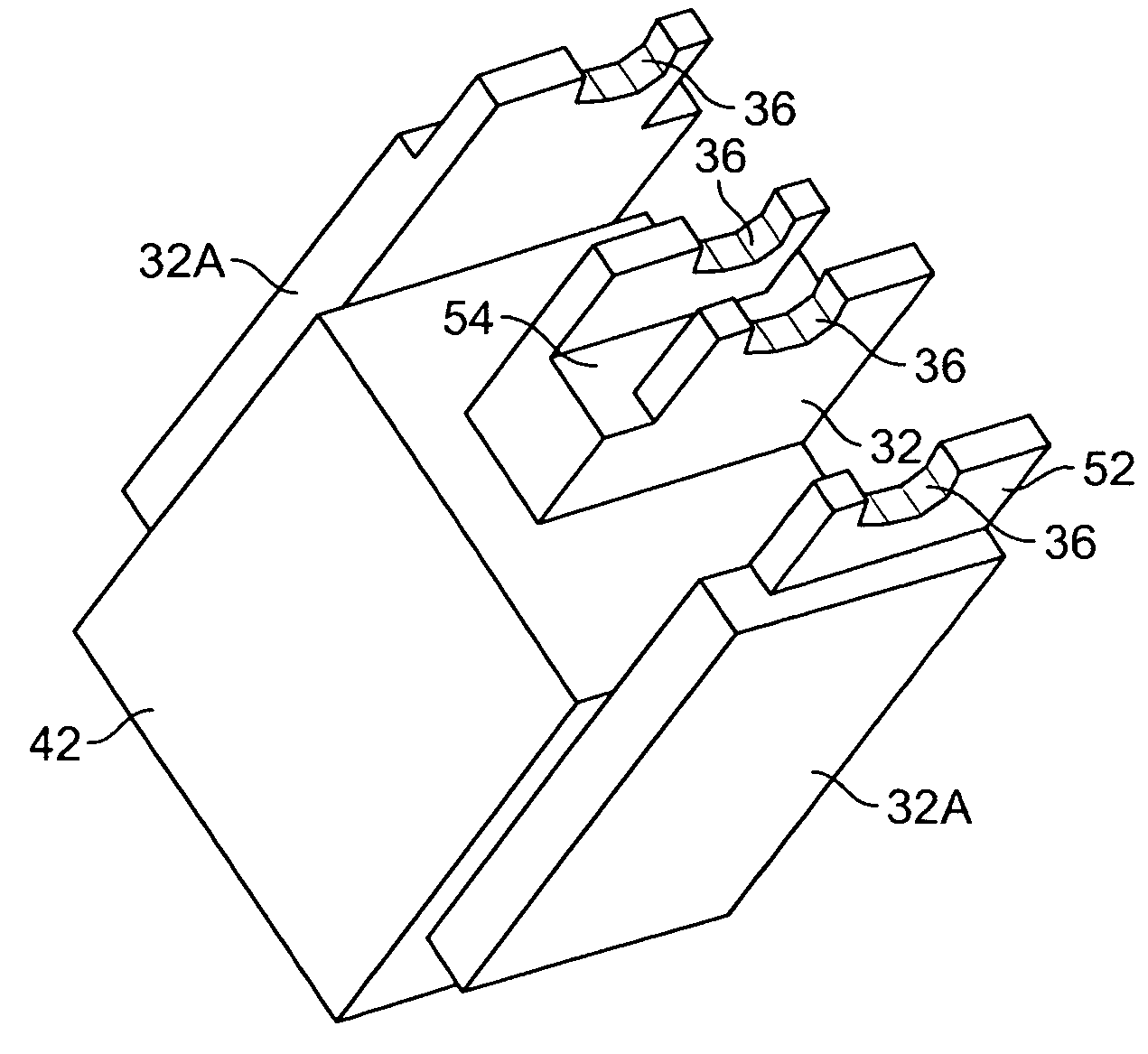
[0028]The present invention satisfies the need for a traveling wave tube having a coupled cavity circuit that utilizes thicker polepieces in order to utilize higher power electron beams, while at the same time maintaining the desired size and number of cavities between the polepieces. In the detailed description that follows, like element numerals are used to describe like elements illustrated in one or more figures.

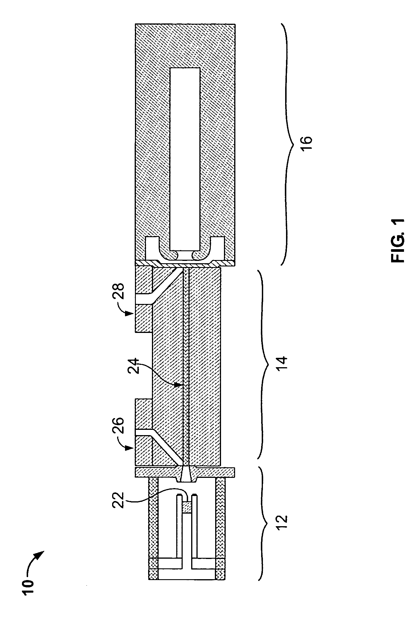
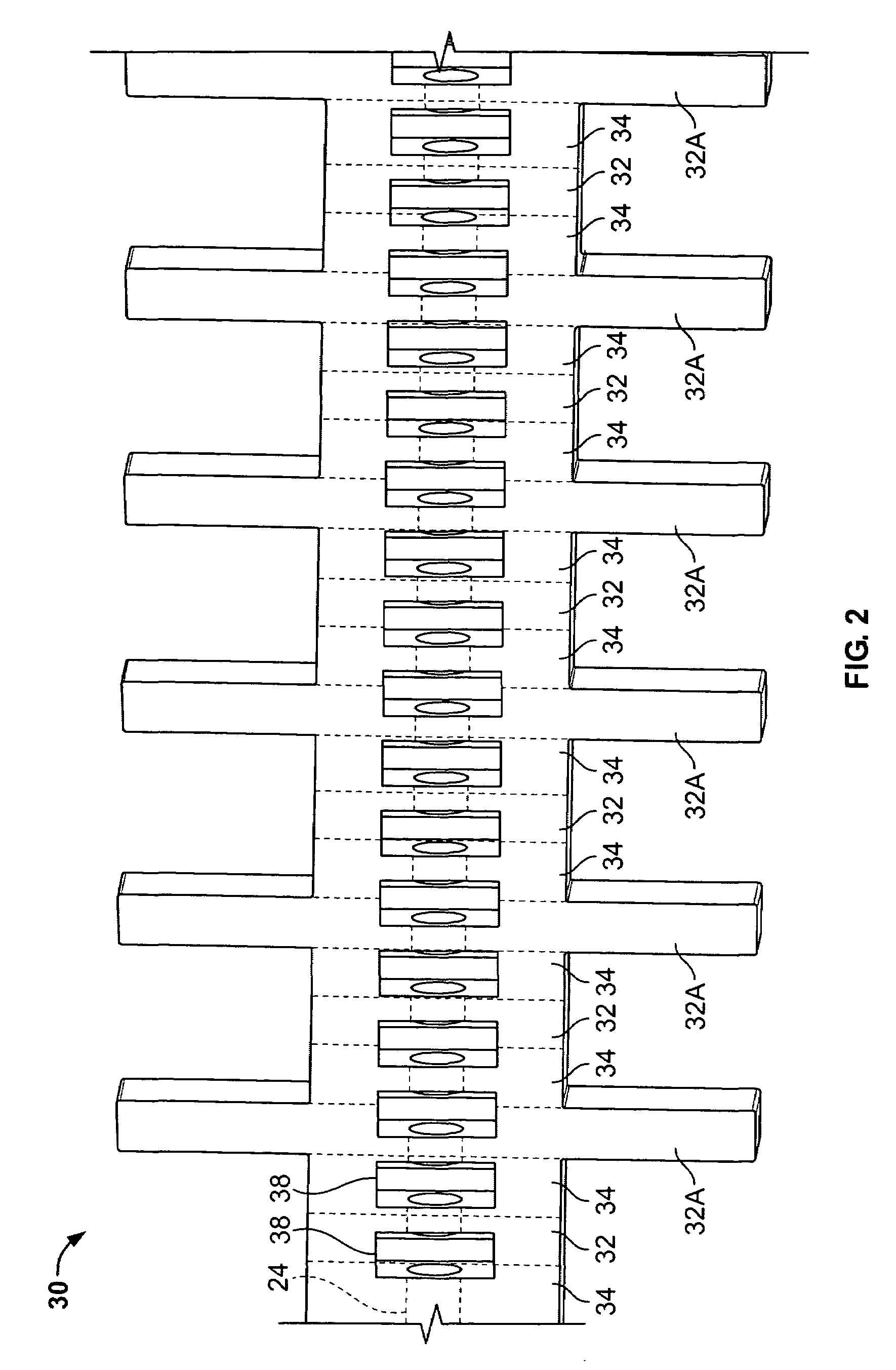
[0029]Referring first to FIG. 1, an exemplary traveling wave tube (TWT) amplifier 10 is illustrated as including an electron gun 12, an interaction section 14, and a collector 16. The electron gun 12 generally includes a cathode surface 22 with a thermionic heating element disposed below the surface. An electron beam is drawn from the cathode surface 22 by activating the heating element and applying a highly negative voltage to the cathode. The electron beam travels axially through a drift tube 24 formed in the interaction section and is deposited in the collector 16. Th...


PUM


Abstract

An amplifying device comprises an electron gun emitting an electron beam, a collector spaced from the electron gun, the collector oriented to collect electrons of the electron beam emitted from the electron gun, and an interaction structure interposed between the electron gun and the collector. The interaction structure defines an electromagnetic path along which an applied electromagnetic signal interacts with the electron beam. The interaction structure further comprises a plurality of polepieces and a plurality of magnets, the polepieces each having an aligned opening to collectively provide an electron beam tunnel having an axis extending between the electron gun and the collector to define an electron beam path for the electron beam. The polepieces provide a magnetic flux path to the electron beam tunnel from the magnets. More particularly, the interaction structure further includes plural cavities defined therein interconnected to provide a coupled cavity circuit. At least one of the plurality of polepieces separate adjacent ones of the plural cavities and have an iris for coupling the electromagnetic signal therethrough. At least one of the plurality of polepieces further has a void aligned perpendicularly to the beam tunnel axis.

Description

RELATED APPLICATION DATA[0001]This application claims priority pursuant to 35 U.S.C. § 119(e) to provisional patent application Ser. No. 60 / 625,306, filed Nov. 4, 2004, for COMPACT W-BAND FOLDED WAVEGUIDE TRAVELING WAVE TUBE, the contents of which are incorporated by reference herein in its entirety.BACKGROUND OF THE INVENTION[0002]1. Field of the Invention[0003]The present invention relates to microwave amplification tubes, such as a traveling wave tube (TWT) or klystron, and, more particularly, to a coupled cavity microwave electron tube that produces a broadband response at high frequencies.[0004]2. Description of Related Art[0005]Microwave amplification tubes, such as TWT's or klystrons, are well known in the art for enabling a radio frequency (RF) signal and an electron beam to interact in such a way as to amplify the power of the RF signal. A coupled cavity TWT typically includes a series of tuned cavities that are linked or coupled by irises (also know as notches or slots) fo...

Claims


Application Information

Patent Timeline
Patent Type & Authority Patents(United States)
IPC IPC(8): H01J25/34
CPCH01J23/24
Inventor THEISS, ALAN
Owner L 3 COMM CORP
Why Eureka
Try Eureka