Coiled optical fiber assembly for measuring pressure and/or other physical data

a technology of optical fiber and assembly, applied in the field of measuring data, can solve the problems of limiting the amount of fiber bragg gratings that can be distributed along the length of an optical fiber, shifting the wavelength of light it reflects, and initiating the variation of transmission loss caused by deformation

Active Publication Date: 2008-01-01
SHELL USA INC
View PDF15 Cites 50 Cited by
  • Summary
  • Abstract
  • Description
  • Claims
  • Application Information

AI Technical Summary

Problems solved by technology

This deformation initiates variation of transmission losses in optical signals transmitted from one end towards another end of the coiled fiber.
These known systems are configured to detect an average pressure exerted on the carrier body and are not designed for use as Distributed Pressure Sensors (DPS) which detect the pressure exerted at different locations along the length of the carrier body and map pressure variations along the length of the carrier body.
Variation of the spacing between a pair of such disruptions, for example due to strain induced by pressure and / or temperature, will cause a shift in the wavelength of the light it reflects.
Fiber Bragg grating optical sensor systems can be used for distributed pressure measurement along the length of an elongate carrier tube, but the currently available signal distinguishing techniques limit the amount of Fiber Bragg gratings that can be distributed along the length of an optical fiber.
Furthermore Fiber Bragg gratings provide fixed sensor sections in an optical fiber, so that pressure and / or other measurements can only be performed in pre-selected section of the fiber, which are subsequently positioned at pre-selected locations where the measurements are to be made.
Thus the known hydrophone is configured to detect variation of the isotropic pressure in the water surrounding the hydrophone and is not suitable for use as a DPS. U.S. Pat. Nos. 5,765,948 and 5,825,804 disclose fiber optical Distributed Temperature Sensor (DTS) systems wherein solely the temperature distribution along the length of an optical fiber is determined on the basis of optical time domain reflectometry, wherein use is made of the Raman spectrum of the backscattered light, which contains temperature information.

Method used


Image

  • Coiled optical fiber assembly for measuring pressure and/or other physical data
  • Coiled optical fiber assembly for measuring pressure and/or other physical data
  • Coiled optical fiber assembly for measuring pressure and/or other physical data

Examples


Embodiment Construction

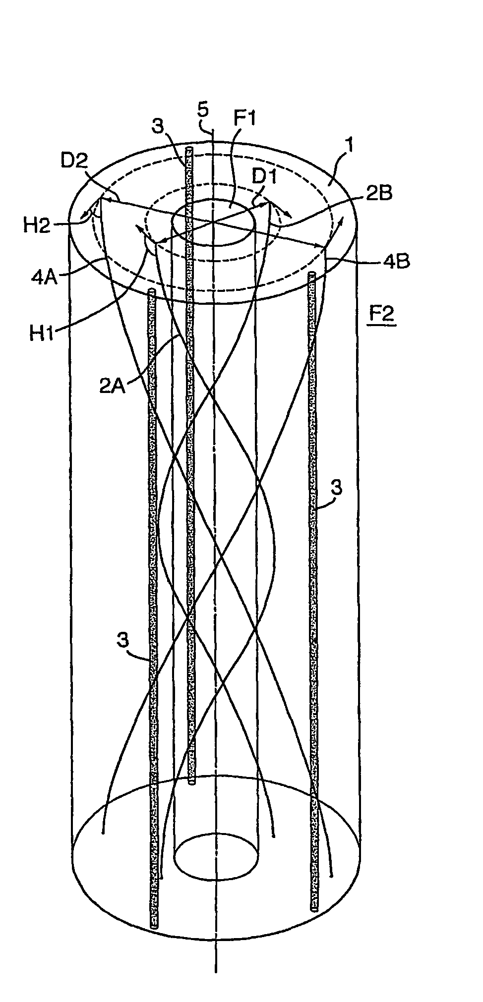
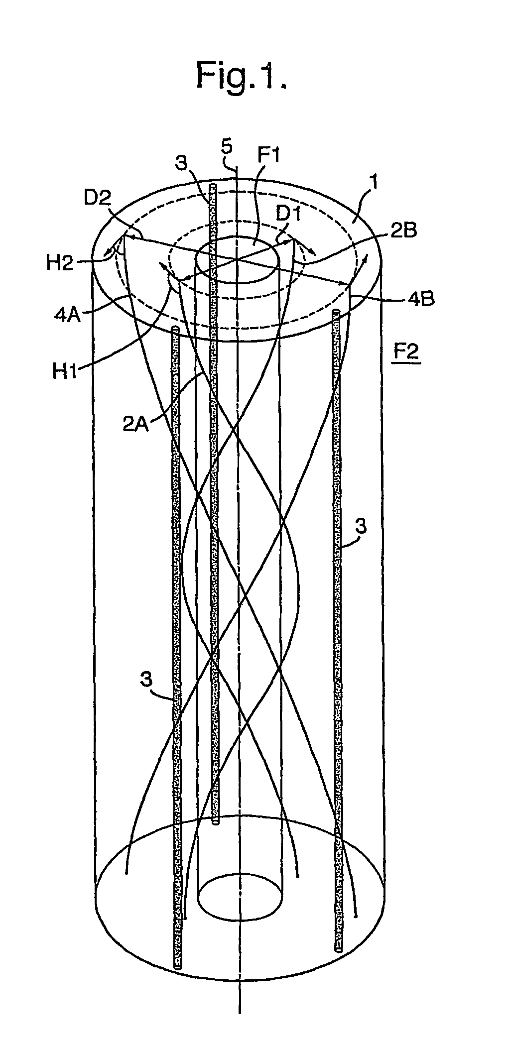
[0018]In FIG. 1 there is shown an elastomeric flexible carrier tube 1 in which three steel longitudinal reinforcement cables 3 and an inner and outer pair of helical optical fibers 2A-2B and 4A-4B are embedded.

[0019]The interior of the carrier tube 1 is filled with a first fluid F1 and the tube 1 is surrounded by a second fluid F2 such that a pressure difference between the fluids F1 and F2 generates a circumferential expansion or contraction of the carrier tube 1, whereas the longitudinal reinforcement cables 3 inhibit simultaneous longitudinal elongation or contraction of the carrier tube 1 as a result of said pressure difference and of the weight of the carrier tube 1 and other forces, such as flotation and friction, acting on the carrier tube 1.

[0020]The inner pair of optical fibers 2A-2B is wound at a diameter D1 and, when seen from above, in a clockwise direction, relative to a longitudinal axis 5 of the tube 1 and at a first helix angle H1.

[0021]The outer pair of optical fibe...


PUM

PropertyMeasurementUnit
pressureaaaaaaaaaa
wavelengthaaaaaaaaaa
lengthaaaaaaaaaa

Abstract

A method and system are disclosed for measuring pressure and other physical data, such as the temperature, elongation, torsion and bending at any point along the length of an elongate carrier tube by means of one or more coiled optical fibers that are embedded in the wall the tube such that deformation of the carrier tube induces strain in each optical fiber. In use a pulsed laser light source transmits a sequence of light pulses of a selected wavelength from an upstream end of each fiber into a coiled substantially uniform light guide channel provided by the optical fiber and a light sensor assembly detects any shift in wavelength of the light pulses backscattered from various locations along the length of the light guide channel. A signal processing assembly then calculates a strain pattern along the length of the fiber, and a pressure difference between the interior and exterior of the tube, at various locations along the length of the carrier tube. Preferably several fibers are wound at different pitch angles and in different directions and at different diameters in the wall of the carrier tube and the signal processing assembly calculates bending, torsion and both radial and axial deformation of the carrier tube on the basis of a comparison of the strain patterns induced on different optical fibers.

Description

[0001]The present application claims priority on European Patent Application 03075647.2 filed Mar. 5, 2003.FIELD OF THE INVENTION[0002]The invention relates to a method and system for measuring data by means of one or more optical fibers.BACKGROUND OF THE INVENTION[0003]The invention relates to a method and system for measuring pressure and / or other physical data, such as temperature and deformation due to axial, torque and / or bending stresses by means of one or more optical fibers that are embedded in a deformable carrier tube.[0004]Various fiber optical systems are known for measuring pressure and / or temperature over long distances.[0005]Japanese patent publications JP6043056, JP9026370, JP6148017, JP60219503, JP2000-018981 disclose fiber optical pressure sensor systems, wherein a coiled optical fiber is embedded in a flexible tubular or cylindrical carrier body such that deformation of the carrier body will cause variation of the curvature and shape of the coiled optical fiber. T...

Claims


Application Information

Patent Timeline
Patent Type & Authority Patents(United States)
IPC IPC(8): G02B6/00G01L11/02
CPCE21B47/01E21B47/06E21B47/065E21B47/102E21B49/006G01L11/025E21B47/07E21B47/113
Inventor VAN DER SPEK, ALEXANDER MICHAEL
Owner SHELL USA INC
Why Eureka
Try Eureka