Inkjet recording method and inkjet recording apparatus

a recording method and inkjet technology, applied in the field of inkjet recording methods and inkjet recording apparatuses, can solve the problems of dye, poor light resistance, deterioration of image quality,

Inactive Publication Date: 2008-01-08
KONICA MINOLTA INC
View PDF13 Cites 21 Cited by
  • Summary
  • Abstract
  • Description
  • Claims
  • Application Information

AI Technical Summary

Benefits of technology

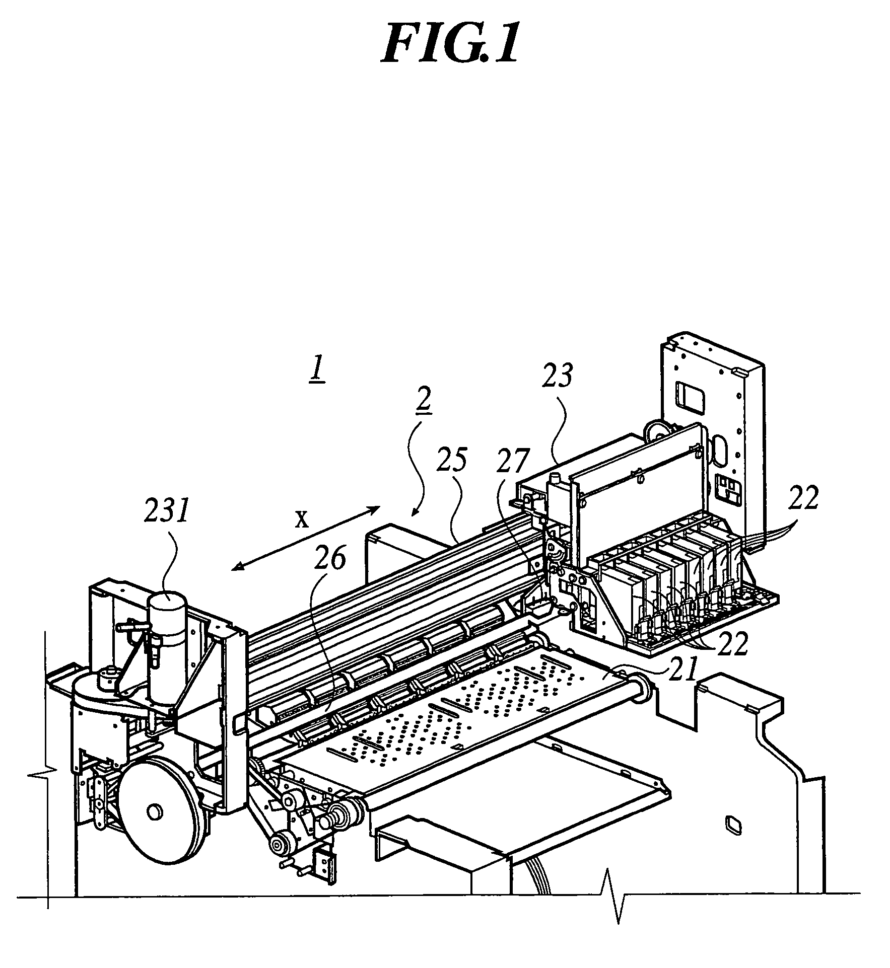
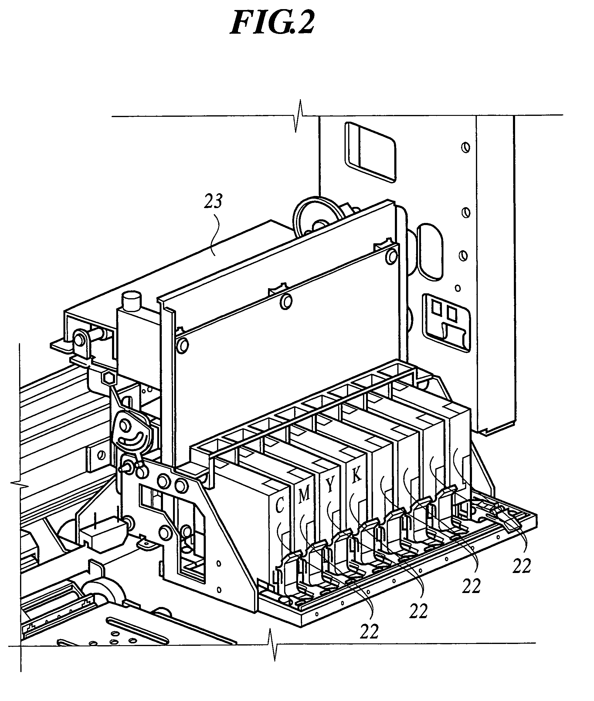
[0056]The color inks and invisible ink are supplied to each recording head passing through a tube for piping from a cartridge for recording ink which is not shown in the figure. As shown in FIGS. 1 and 2, eight pieces of recording heads 22 are disposed side by side along the scanning direction, and the recording head is composed of the first recording head for color inks, which are used for inks such as light color inks and special color ink as well as 4 color inks of cyan (C), magenta (M), yellow (Y) and black (K) and 3 special color inks, and respectively, and the second recording head for the invisible ink. The above embodiment shows the case where four inks of C, M, Y and K and special color ink are used. However, the same effect of the invention can be obtained in the inkjet printer where pale color ink is used in combination with C, M, Y and K for recording.
[0057]Next, An image forming method of the thinned-out image is illustrated, where the first recoding head jetting color inks scans a plural times at a same recording area of a recording medium to form the thinned-out image according to a thinning-out pattern irregular between each of the scanning steps.
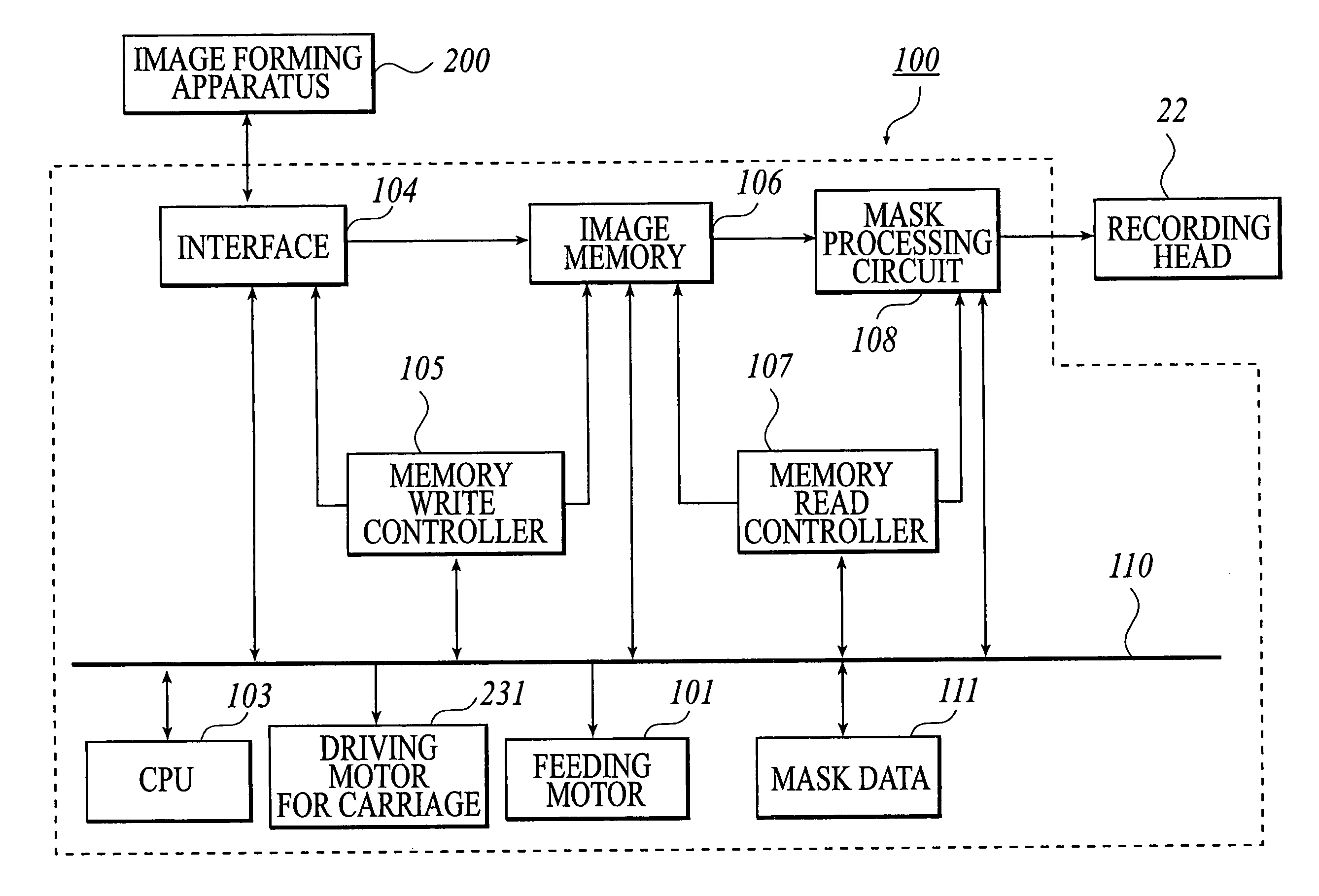
[0058]First, a control section of the inkjet printer 1 is illustrated in reference to FIG. 4. FIG. 4 is a block diagram representing the control section of the inkjet printer 1.
[0059]As shown in FIG. 4, the control section 100 is configured by connecting a feeding motor 101 to feed the recording medium, CPU 103, an interface 104, a driving motor 231 for the carriage, a memory write controller 105, an image memory 106, a memory read controller 107, and a mask processing circuit 108 through a bus 110 as is shown. A detailed configuration of the mask processing circuit 108 is described below. The recording heads 22 of the inkjet printer 1, respective driving sections and the like are also connected to the control section 100.
[0060]The control section 100 controls feeding of the recording medium, scanning operation of the carriage 23 and color inks jetting of the recording heads 22, and the like. As is shown in FIG. 4 and FIG. 5, an image forming apparatus 200 such as computer is connected. The image forming apparatus 200 forms an image with multiple colors based on input signals. In this instance, an application program 201 which operates inside the image forming apparatus 200 displays the image on a monitor 300 through a video driver 202 with processing the image. When this application program 201 puts an image formation direction in motion, the printer driver 203 of the image forming apparatus 200 receives image data for the image formation from the application program 201, and the image data are converted into signals capable of forming the image in the inkjet printer 1.
[0061]The printer driver 203 comprises a rasterizer 204 which converts the image data dealt in the application program 201 into image gradation data including color information of dot units, a color gradation compensation module 205 which compensates the image gradation data in accordance with color density property and gradation property of the inkjet printer 1, and a halftone module 206 which produces the image data of so-called halftone where a density at a certain area is expressed by the presence or absence of the recording inks at dot units from the image data after the color compensation. A module 207 which performs the thinning-out mask processing can be also incorporated in this printer driver. In that case, a mask setting can be changed depending on a medium type used for the printing, and thus more flexible control is possible than the processing in the printer. When the mask processing circuit 108 is used, the processing at the module 207 is not performed. Conversely, when the mask processing is performed at the module 207, the processing at the mask processing circuit 108 is not performed. Also, it is possible to download a mask pattern every printing from the image processing apparatus 200.

Problems solved by technology

In particular, with respect to the uniformity, slight dispersion of nozzle units which occurs in difference of multihead fabrication steps influences jetting amounts and jetting directions of inks at respective nozzles, and becomes a cause which finally deteriorates image quality as uneven density of a printed image.
Also, speed variation at a main scanning of a carriage where heads are loaded, variation of sub scanning paper feeding amount of the recording medium, and variation of a distance between a recording medium surface and a nozzle face on the recording medium cause deterioration of the image.
The dye, however, has drawbacks of poor light resistance because dye molecules tend to break by photochemical reaction.
It is an actual state that the inkjet recording image using the dye inks is the high image quality but the poor image stability against light, and the technology which is superior to silver halide photographs in the light of stability has not appeared yet.
As a result, it was impossible to obtain an image of high definition such like a silver halide photograph.
However, when an inkjet image recording according to the thinning-out pattern without regularity is performed using the pigment inks, a dot position formed at each scanning has no regularity.
As a result, the respective ink droplets are mixed one another, which causes aggregation of pigment particles, and a phenomenon that glossiness of an image portion becomes uneven occurs.
Even if the invisible ink is adhered onto a recording medium, it is impossible to obtain an image of high definition and high quality having transparency feeling such as a silver halide photograph.
Besides, it has been found that due to using the mask pattern without regularity, a probability that different color dots are adjacently printed becomes high, and the formation of image at high definition becomes difficult because the pigment particles having different color tone are mixed on the recording medium.
This is because when using the regular thinning-out pattern, the position of each ink formed on the recording medium at one scanning can be finely controlled and mixture of the dots can be effectively inhibited whereas it is difficult to perform such a control in the case without regularity.

Method used


Image

  • Inkjet recording method and inkjet recording apparatus
  • Inkjet recording method and inkjet recording apparatus
  • Inkjet recording method and inkjet recording apparatus

Examples


example 1

>

[Manufacture of Recording Medium 1]

[Manufacture of Support]

[0247]Base paper was made by preparing a slurry solution containing 1 part of polyacrylamide, 4 parts of ash (talc), 2 parts of cationized starch, 0.5 parts of polyamide epichlorohydrin resin and various addition amounts of alkylketene dimer (sizing agent) for 100 parts of wood pulp (LBKP / NBSP=50 / 50) and using a fourdrinier machine such that a weighing is 170 g / m2. A support 1, which was an absorbable support and has a smooth surface, was made by giving a calendar treatment to this base paper.

[0248]After giving corona discharge to this support 1, a hardener-containing gelatin undercoating layer was applied at 0.04 g / m2 in terms of a solid content, and on a back face, a styrene / acryl type emulsion containing silica fine particles (matting agent) with a mean particle size of 1 μm and a small amount of a cationic polymeric molecule (conducting agent) was applied such that a dried film thickness is about 0.5 μm.

[Preparation of ...


PUM

PropertyMeasurementUnit
sizeaaaaaaaaaa
particle sizeaaaaaaaaaa

Abstract

An inkjet recording method and apparatus including: forming a color image with color inks and an invisible ink by while scanning a first recording head multiple times on a same recording area, forming a thinned-out image, and jetting an invisible ink from a second recording head in accordance with an adhering amount of the color inks per, wherein a nozzle pitch of the first recording head is from 10 to 50 μm, the color inks comprise C, M, Y and BK inks and at least one special color ink, the color inks contain pigments, at least one organic solvent with high boiling point and water, a dot formed color inks has a size of 10 to 50 μm, and the recording medium has a transferred amount at 0.04 seconds of absorption time of 10 ml / m2 or more, a micro-porous layer containing inorganic fine particles and a hydrophilic binder.

Description

BACKGROUND OF THE INVENTION[0001]1. Field of the Invention[0002]The present invention relates to a novel inkjet recording method and inkjet recording apparatus.[0003]2. Description of Related Art[0004]An inkjet recording mode is one for recording images and texts by flying minute droplets of ink to adhere onto a recording medium by various operation principles, and has advantages such as relatively high speed, low noise and easiness of multiple coloration. In the above inkjet recording mode, various improvements have been performed in various fields such as an ink, inkjet recording medium and inkjet recording apparatus, and at present, the mode has become rapidly popular for various fields such as various printers, facsimiles and computer terminals. In particular, recently high-quality picture technology in the printer has been improved, and its level has come at a picture quality of photograph.[0005]As the inkjet recording apparatus used in the inkjet recording mode, for enhancing ...

Claims


Application Information

Patent Timeline
Patent Type & Authority Patents(United States)
IPC IPC(8): G01D11/00B41J2/01B41M5/00B41M5/50B41M5/52B82Y30/00C09D11/00C09D11/322C09D11/326C09D11/38
CPCB41J2/2114
Inventor MATSUZAWA, TAKAHIROTOMOTAKE, ATSUSHINAKAZAWA, KENZOSUGIHARA, MIYAKO
Owner KONICA MINOLTA INC
Why Eureka
Try Eureka