
Satellite digital radio broadcast receiver

a digital radio and receiver technology, applied in the field of satellite digital radio broadcast receivers, can solve the problems of requiring complicated control process, idle time before sound reproduction, and inability to adapt to mobile stations, and achieve the effect of reducing costs

Inactive Publication Date: 2008-01-08
JVC KENWOOD CORP A CORP OF JAPAN
View PDF21 Cites 23 Cited by
  • Summary
  • Abstract
  • Description
  • Claims
  • Application Information

AI Technical Summary

Benefits of technology

[0023]It is an objective of the present invention to provide a satellite digital radio broadcast receiver capable of eliminating the above-described disadvantages and improving the disturbance wave elimination characteristics with a simple structure.
[0026]As above, according to the satellite digital radio broadcast receiver of this invention, only one series can suffice for the input signals to the integrated circuit so that the receiver can be made compact and the cost can be reduced.

Problems solved by technology

Since the service area is the North America, if a Geo stationary satellite only is used, the elevation angle of an antenna is low so that this is not suitable for mobile stations.
Further, since a digital modulation method is incorporated for the satellite digital radio broadcast, if the reception signal is once intercepted, there is some idle time before sounds can be reproduced, because data synchronization and the like are necessary.
A complicated control process is therefore required such as matching the switching timing for signal level control to the data transition period and fixing the synchronization circuit and the like during such period.
If a signal cannot be received once because of the switching hysteresis control, even if the disturbance signal level lowers somewhat, it is not so fast until the reception is recovered.

Method used


Image

  • Satellite digital radio broadcast receiver
  • Satellite digital radio broadcast receiver
  • Satellite digital radio broadcast receiver

Examples


Embodiment Construction

[0035]Description will be made on a satellite digital radio broadcast receiver according to an embodiment of the invention.

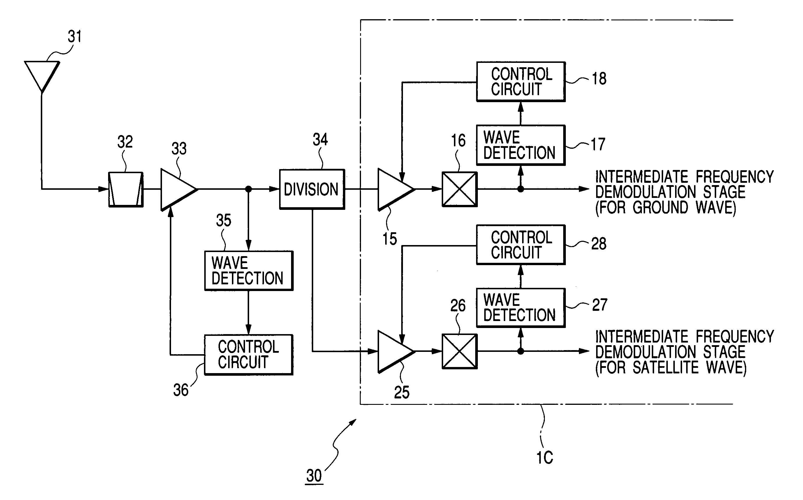
[0036]FIG. 6 is a block diagram showing the structure of a tuner unit of a satellite digital radio broadcast receiver according to the embodiment of the invention.

[0037]In the satellite digital radio broadcast receiver 30 of the embodiment, an antenna 31 receives a satellite wave signal and a ground wave signal. The band of the received signal is limited by a band-pass filter 32, and an output of the band-pass filter 32 is supplied to and amplified at a voltage control type variable gain amplifier 33. An output signal from the voltage control type variable gain amplifier 33 is supplied to a two-way distributor 34 which inputs two-way distributed output signals to variable gain amplifiers 15 an 25 of an integrated circuit IC, respectively. The integrated circuit IC has the same structure as the integrated circuit IC shown in FIG. 3, and so the description of the ...


PUM


Abstract

A satellite digital radio broadcast receiver has an integrated circuit including a first reception series for processing a satellite wave signal from a satellite and a second reception series for processing a ground wave signal from a repeater in order to receive both the satellite wave signal and the ground wave signal having the same broadcast contents and different modulation methods. The receiver has an automatic gain control unit for amplifying a signal from a single antenna at a variable gain amplifier, and in accordance with the level of a signal outputted from the variable gain amplifier, for controlling the gain of the variable gain amplifier; and a two-way distributor for distributing an output of the automatic control unit to two distribution outputs, wherein one distribution output of the two-way distributor is supplied to the first reception series of the integrated circuit and the other distribution output is supplied to the second reception series of the integrated circuit.

Description

BACKGROUND OF THE INVENTION[0001]1. Field of the Invention[0002]The present invention relates to a satellite digital radio broadcast receiver for receiving a broadcast program having the same contents but different modulation methods.[0003]2. Related Background Art[0004]Satellite digital radio broadcasting from a plurality of elliptical orbit satellites moving along a so-called figure 8 orbit is presented, for example, by US SIRIUS Satellite Radio Incorporated. The outline of the whole system of satellite broadcast is shown in FIG. 1. This broadcast system uses one Geo stationary satellite and three elliptical orbit satellites (not stationary satellite) each moving along a figure 8 orbit. Since the service area is the North America, if a Geo stationary satellite only is used, the elevation angle of an antenna is low so that this is not suitable for mobile stations. An elliptical orbit satellite moves along the figure 8 orbit so that it does not always locate overhead. Therefore, a r...

Claims


Application Information

Patent Timeline
IPC IPC(8): H04H1/00H04B1/16H04N7/20
CPCH04H40/90H04H20/74
Inventor HIROSE, KOJI
Owner JVC KENWOOD CORP A CORP OF JAPAN
Features
  • Generate Ideas
  • Intellectual Property
  • Life Sciences
  • Materials
  • Tech Scout
  • Unparalleled Data Quality
  • Higher Quality Content
  • 60% Fewer Hallucinations
Learn More