Luminescent sheet covering for LEDs

a technology of leds and sheets, applied in the direction of electric lighting sources, semiconductor devices, electric light sources, etc., can solve the problems of reducing light output, difficult to obtain uniform coating distribution, and difficult to produce uniform thickness from one part of led to another

Active Publication Date: 2008-01-15
GE LIGHTING SOLUTIONS LLC
View PDF22 Cites 114 Cited by
  • Summary
  • Abstract
  • Description
  • Claims
  • Application Information

AI Technical Summary

Benefits of technology

[0011]One advantage of the present application resides in improved uniformity of a phosphor coating.

Problems solved by technology

Some of the radiation, which is scattered or reflected back onto the LED, can be absorbed by the chip, reflector, submount, and / or lead structure resulting in a decrease of the light output.
However, because the LEDs and LED components are small and often irregular in shape, it is difficult to obtain a uniform distribution of coating.
Furthermore, it is difficult to produce a uniform thickness from one part of the LED to another.

Method used


Image

  • Luminescent sheet covering for LEDs
  • Luminescent sheet covering for LEDs
  • Luminescent sheet covering for LEDs

Examples


Embodiment Construction

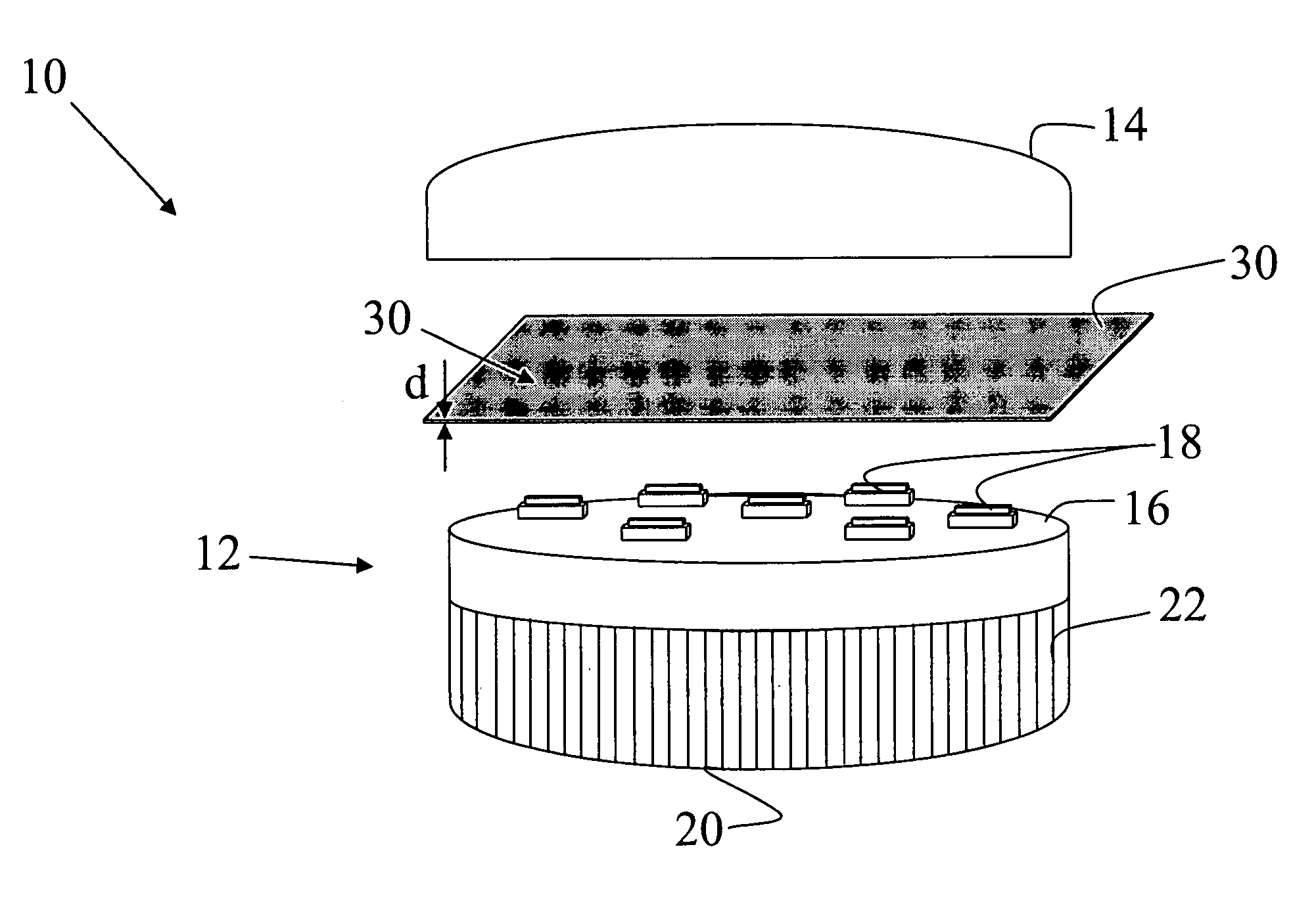
[0020]With reference to FIG. 1, an LED light assembly 10 comprises a light engine 12 and an enclosure 14 which surrounds the radiation emitted by the light engine 12. The light engine 12 includes an interconnect system or boards or mounting surface or printed circuit board 16 for mounting and connecting light emitting devices or LEDs 18 such as chip or packaged LEDs emitting blue or ultra-violet (UV) radiation. A heatsink 20, including a plurality of heat dissipating elements such as wings 22, is disposed in thermal connection with the LEDs 18 and the interconnect system 16 to dissipate heat generated by the LEDs 18. Preferably, the interconnect system 16 includes circuitry for powering the LEDs 18 and leads for electrical communication with a power source. The interconnect boards 16 are selected from commercially available circuit boards, such as the circuit boards available from BERGQUIST, to provide suitable means for removing heat generated by the LEDs 18 and dissipating it in t...


PUM


Abstract

A lighting apparatus comprising at least one light emitting diode is disposed on an interconnect board to emit ultraviolet or blue radiation. A polymeric layer including a luminophor is disposed about the lighting apparatus to convert at least a portion of the radiation emitted from the LED into visible light. The polymeric layer is shrinkable to conform to a shape enclosing the light emitting diode.

Description

BACKGROUND[0001]The present application relates to the art of the LED lighting systems that produce visible light. It finds application in general purpose lighting and will be described with particular reference thereto. Those skilled in the art will appreciate the applicability of the present application to a variety of applications such as ornamental, special effects lighting, and other.[0002]Typically, the LED lighting systems, which produce white or visible light incorporate blue LEDs, are coated with phosphor that converts some of the blue light radiation to a complimentary color, e.g. yellow-green emission. Combined blue, yellow and green emissions produce a white light.[0003]Some white LED lighting systems unitize a blue LED chip coated with phosphors which are designed to convert some of the blue radiation into complementary colors. An example of a commonly used phosphor for this purpose is the yellow emitting yttrium gadolinium aluminum garnet phosphor activated with Ce3+. ...

Claims


Application Information

Patent Timeline
Patent Type & Authority Patents(United States)
IPC IPC(8): H01L31/0203H01L33/50
CPCH05B33/145H05B33/22H01L33/505
Inventor SOULES, THOMAS F.CHEN, CHEN-LUN HSINGRADKOV, EMIL
Owner GE LIGHTING SOLUTIONS LLC
Why Eureka
Try Eureka