Method and apparatus for estimating the position of a moving part of a linear actuator

a linear actuator and moving part technology, applied in the direction of motor/generator/converter stopper, ignition automatic control, dynamo-electric converter control, etc., can solve the problems of high mechanical noise, many limitations of stepping motors, and inability to speed up, so as to reduce the cost of the magnetic scale, simple and rapid calculation, and enhance the resolution

Active Publication Date: 2008-01-15
TRANSPACIFIC IP LTD
View PDF8 Cites 0 Cited by
  • Summary
  • Abstract
  • Description
  • Claims
  • Application Information

AI Technical Summary

Benefits of technology

[0008]An object of the present invention is to provide a method for estimating the position of a moving part of a linear actuator, with the advantage of simple and rapid calculation, thereby reducing the cost of the magnetic scale and enhancing the resolution.
[0009]Another object of the present invention is to provide an apparatus for estimating the position of a moving part of a linear actuator, with the advantage of being simple and rapid, thereby further reducing the system cost and further enhancing the resolution.
[0017]According to a preferred embodiment of the present invention, the above method for estimating the position of a moving part of a linear actuator employs the calculation and analysis of the microprocessor instead of the expensive mixed-signal interpolation chip, such that the calculation process is much simpler and more rapid compared with the conventional method, thereby, the cost can be reduced, and the defect of the slow and redundant conventional algorithms can be avoided. Moreover, the present method uses the magnetic signals output by the MR sensor to carry out the calculation by way of linear approximation, and if an ADC with high resolution is used together, the resolution can be achieved to replace the conventional interpolation chip.
[0018]The above apparatus for estimating the position of a moving part of a linear actuator is mainly the implementation of the above method through hardware; therefore, it has the advantages of being simple, rapid, and reducing costs as well. Moreover, the apparatus does not require the microprocessor, such that the system cost can be further reduced. Also, the present apparatus is a hardware architecture, such that the successive random position can be achieved without any resolution problem.

Problems solved by technology

However, stepping motors have many limitations.
For example, the position speed is not fast enough, which is time and power consuming for the system when the position is achieved at a low speed; and relatively high mechanical noise occurs during position operation.
The main defect of this architecture lies in that the price of the mixed-signal interpolation chip 105 is extremely high.
However, the conventional algorithms all require complicated and redundant computations, and require much time for floating-point computation, which adversely influences the position efficiency.

Method used


Image

  • Method and apparatus for estimating the position of a moving part of a linear actuator
  • Method and apparatus for estimating the position of a moving part of a linear actuator
  • Method and apparatus for estimating the position of a moving part of a linear actuator

Examples


Embodiment Construction

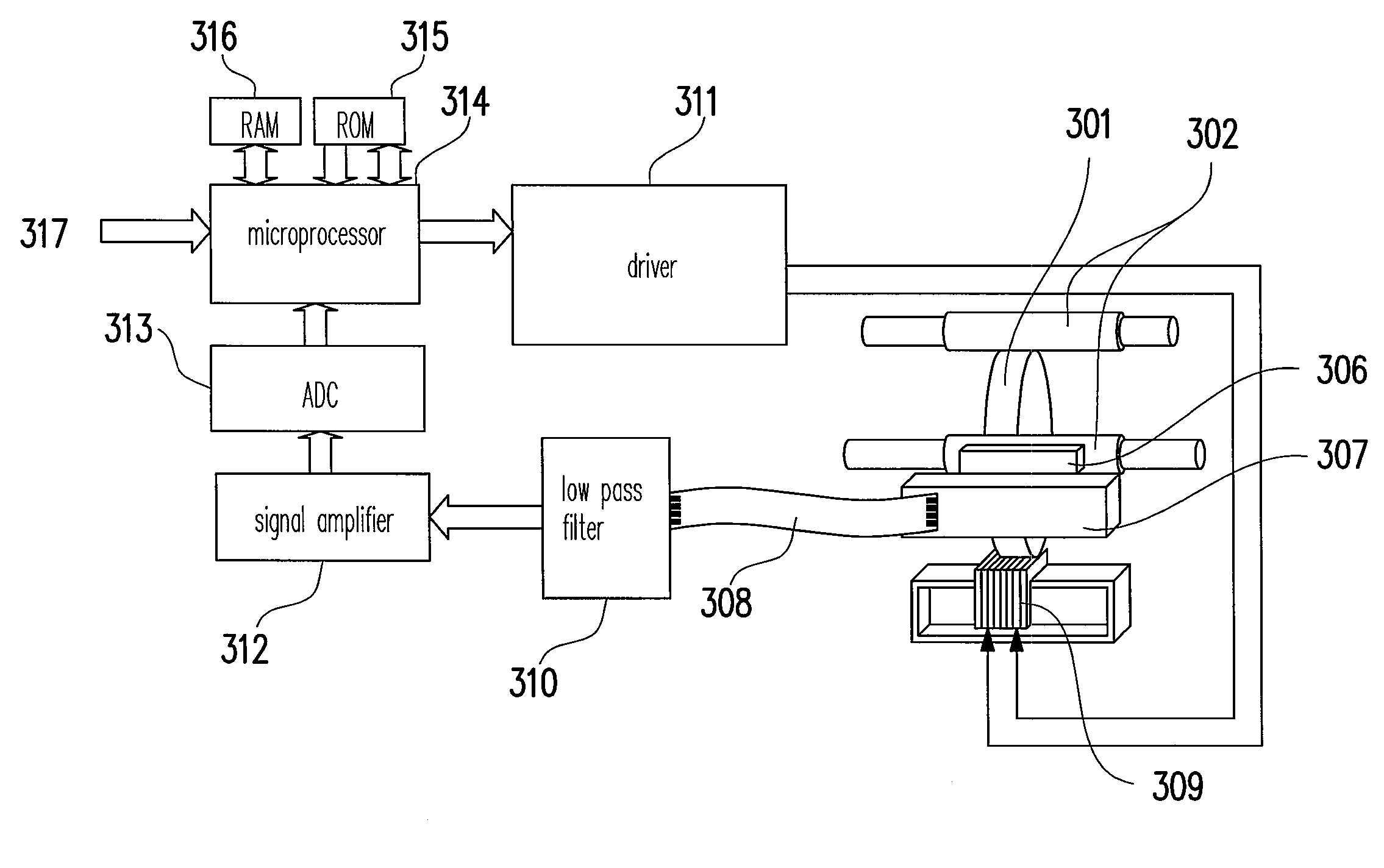
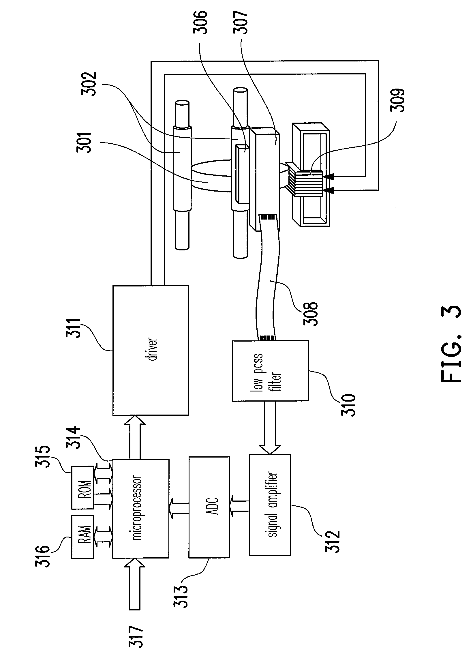
[0034]FIG. 3 is an architecture diagram of a position feedback control for a linear actuator according to an embodiment of the present invention, which uses a digital video camera or digital camera as an example. In FIG. 3, the moving part of the linear actuator comprises a moving coil 309, a lens holder 301, a linear magnetic strip 306 with alternating polarities, and a sleeve tube 302. The digital circuit for controlling the linear actuator comprises a microprocessor 314, an ADC 313, a read-only memory (ROM) 315, and a random access memory (RAM) 316. The microprocessor 314 receives the commands and data 317 from the image digital signal processor (not shown). A driver 311 receives the digital data and control command from the microprocessor 314, and then generates different driving voltages based on the received commands so as to drive the moving part of the linear actuator. When the moving part of the linear actuator moves, an MR sensor 307 shifts relatively to the linear magneti...


PUM


Abstract

A method and an apparatus for estimating the position of a moving part of a linear actuator are provided. The method comprises the following steps. Move the moving part towards a target position. Receive magnetic signals generated by the magneto-resistive sensor of the linear actuator, which include a sine signal and a cosine signal. Then, generate a first square wave, a second square wave, and a regional square wave based on the sine signal and the cosine signal. Generate a saw-tooth wave based on the sine signal, the cosine signal, the second square wave, and the regional square wave. Next, calculate the number of regions which the moving part is across from the origin point based on the first square wave, the second square wave, and the regional square wave. Finally, estimate the current position of the moving part based on the saw-tooth wave and the number of regions.

Description

CROSS-REFERENCE TO RELATED APPLICATION[0001]This application claims the priority benefit of Taiwan application serial no. 94146076, filed on Dec. 23, 2005. All disclosure of the Taiwan application is incorporated herein by reference.BACKGROUND OF THE INVENTION[0002]1. Field of Invention[0003]The present invention relates to a position feedback control architecture of a linear actuator, and more particularly, to a method and apparatus for estimating the position of a moving part of a linear actuator.[0004]2. Description of Related Art[0005]The conventional position actuator generally employs a stepper motor as the driving device. However, stepping motors have many limitations. For example, the position speed is not fast enough, which is time and power consuming for the system when the position is achieved at a low speed; and relatively high mechanical noise occurs during position operation. Therefore, in order to improve the position properties and to efficiently reduce the hardware ...

Claims


Application Information

Patent Timeline
Patent Type & Authority Patents(United States)
IPC IPC(8): H02K41/02G05B11/00
CPCG01B7/003G01D5/24404G01D5/24452G01D5/2448G01D5/2449G01D18/001
Inventor KUO, LI-TEYU, HSING-CHENGLEE, TZUNG-YUANWANG, SHYH-JIER
Owner TRANSPACIFIC IP LTD
Why Eureka
Try Eureka