Low noise block downconverter converting received signal to intermediate frequency signal

a low noise block and downconverter technology, applied in the direction of waveguide devices, electrical equipment, resonances, etc., can solve the problem of increasing the cost of chip components

Inactive Publication Date: 2008-01-15
SHARP KK
View PDF24 Cites 9 Cited by
  • Summary
  • Abstract
  • Description
  • Claims
  • Application Information

AI Technical Summary

Benefits of technology

[0011]Based on the foregoing, a main object of the present invention is to provide a low noise block downconverter employing a low pass filter that achieves attenuation char...

Problems solved by technology

It would increase the cos...

Method used


Image

  • Low noise block downconverter converting received signal to intermediate frequency signal
  • Low noise block downconverter converting received signal to intermediate frequency signal
  • Low noise block downconverter converting received signal to intermediate frequency signal

Examples


Embodiment Construction

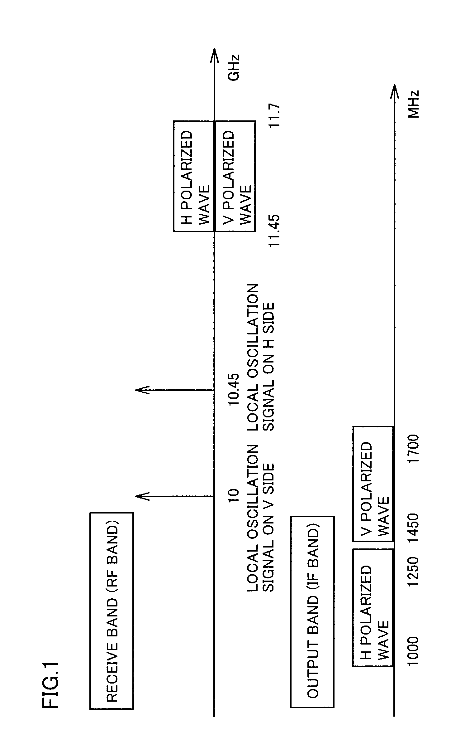
[0026]FIG. 1 shows by way of example the transmission frequency bands of a band stack LNB to which the present invention is applied. In the band stack LNB shown in FIG. 9, the signal of 11.45-11.70 GHz arriving from the satellite has the H polarized wave and the V polarized wave, which are mixed with local oscillation signals of 10.45 GHz and 10 GHz, respectively, by MIX. The H polarized wave and the V polarized wave are thus converted to 1000-1250 MHz and 1450-1700 MHz, respectively.

[0027]To transmit these signals in one cable, as described above, the interference components are removed by HPF and LPF, respectively, before mixing thereof. LPF in this case is inserted into a signal line on the H polarized wave side. The LPF is required to realize very steep attenuation, since the difference between the pass band and the reject band is only 200 MHz.

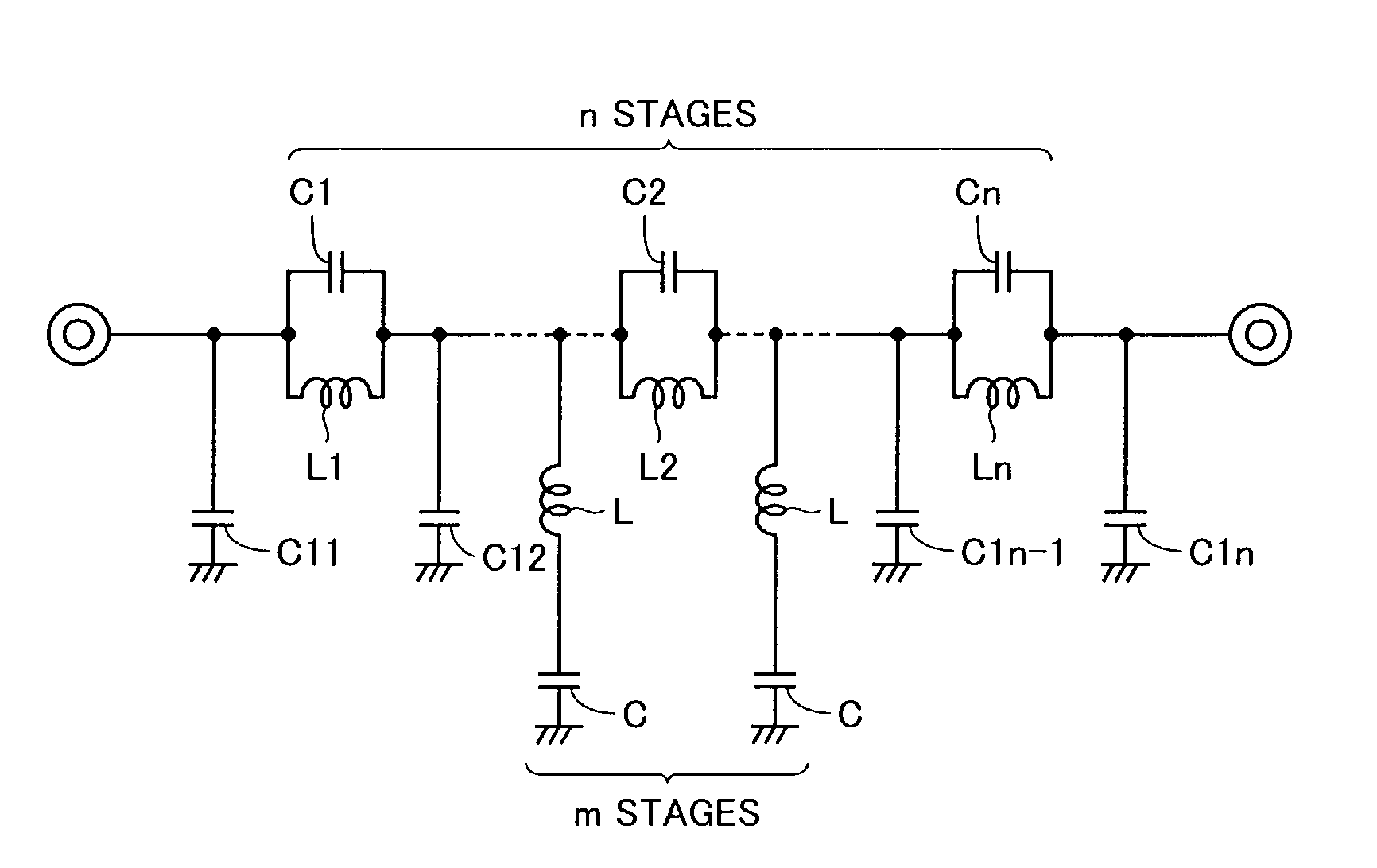
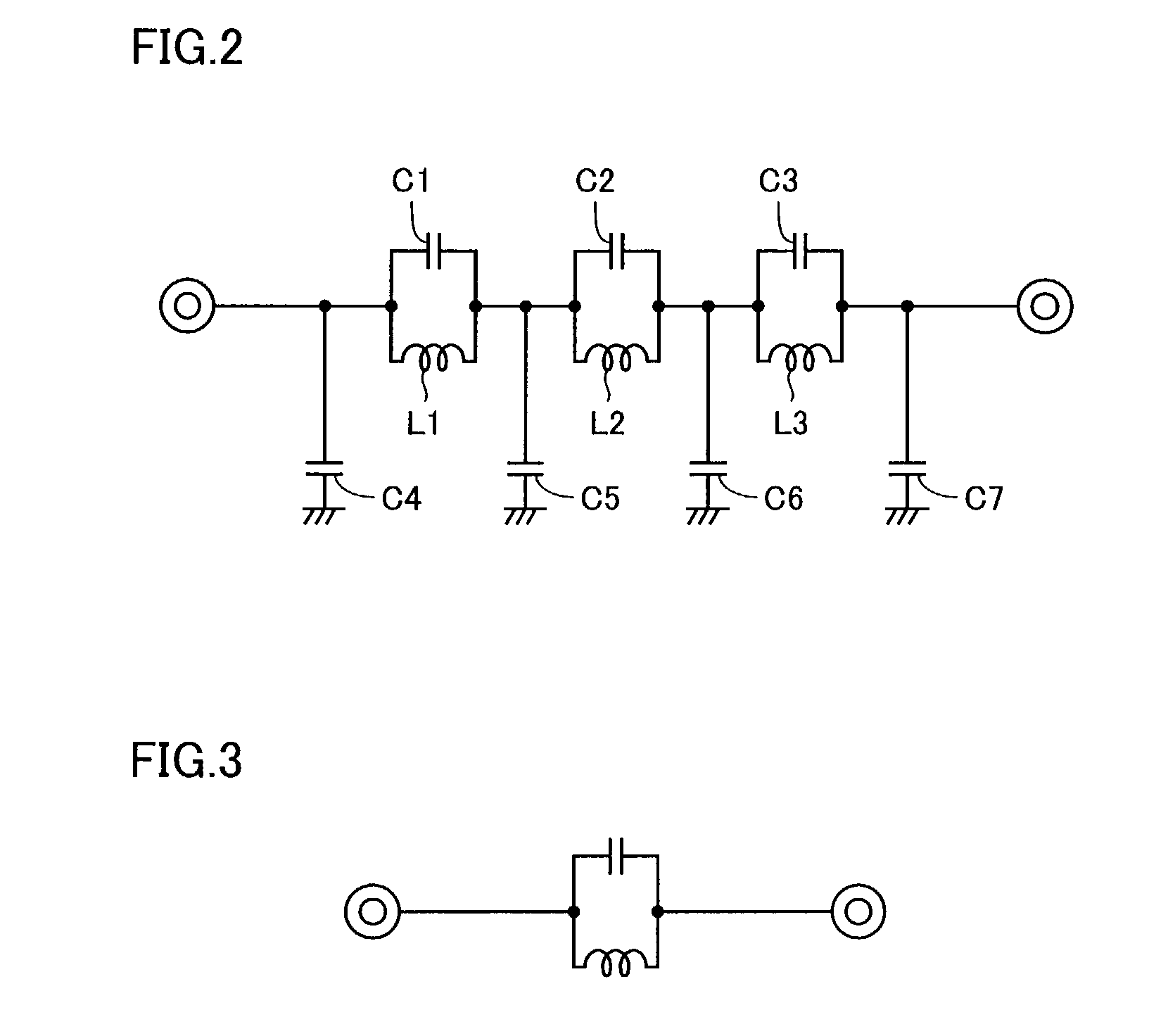
[0028]FIG. 2 shows an LPF used in an embodiment of the present invention, and FIG. 3 shows a parallel resonant trap circuit as a componen...


PUM


Abstract

In a low noise block downconverter converting a right-hand (or horizontally) polarized wave signal and a left-hand (or vertically) polarized wave signal to intermediate frequency signals, one of two filters for removal of interference waves from the intermediate frequency signals on the right-hand (or horizontally) polarized wave side and on the left-hand (or vertically) polarized wave side is formed of a plurality of stages of parallel resonant trap circuits having capacitors and inductors connected in parallel, respectively, which exhibit attenuation characteristic that is wideband and steep and allows great attenuation in the reject band. Thus, it is possible to provide a low noise block downconverter employing an LPF that achieves attenuation characteristic being wideband and steep and allowing great attenuation in the reject band with the least possible number of inductor components that would otherwise increase the cost.

Description

BACKGROUND OF THE INVENTION[0001]1. Field of the Invention[0002]The present invention relates to low noise block downconverters, and more particularly to a low noise block downconverter in a satellite receiver receiving satellite broadcasting.[0003]2. Description of the Background Art[0004]FIG. 7 is a block diagram showing a configuration of a conventional satellite broadcasting receiving system. Referring to FIG. 7, a high-frequency signal in the 12 GHz band (11.45-11.70 GHz) arriving from a broadcasting satellite 100 is received by an antenna 101. Antenna 101 is provided with a low noise block downconverter (hereinafter, referred to as “LNB”) 102. The weak high-frequency signal of the 12 GHz band from broadcasting satellite 100 is frequency-converted to an intermediate frequency (IF) signal of 1 GHz band and low-noise amplified by LNB 102. The resultant low-noise signal of a sufficient level is supplied to a digital broadcasting satellite (DBS) tuner 104 connected as a next stage....

Claims


Application Information

Patent Timeline
IPC IPC(8): H04B1/10H04N7/20H03H7/01H03H7/075H04B1/18H04B1/28
CPCH03H7/0115H03H7/1758H03H7/1766H04B1/28H03H2007/013
Inventor MOTOYAMA, KOJI
Owner SHARP KK
Why Eureka
Try Eureka