Concrete batching facility and method

a technology of concrete and batching equipment, applied in the direction of rotary stirring mixers, transportation and packaging, supply apparatus of sold ingredients, etc., can solve the problems of limited design of mixing units, dusting problems, and failure of devices to achieve the effect of optimizing the production and strength of concr

Active Publication Date: 2008-01-22
MCNEILUS TRUCK & MFG INC
View PDF28 Cites 22 Cited by
  • Summary
  • Abstract
  • Description
  • Claims
  • Application Information

AI Technical Summary

Benefits of technology

[0023]By means of the present invention, there is provided a concrete batching system pre-mix arrangement that includes a controlled ingredient supply aspect to measure and control both wetting agent and cementitious ingredient feeds in relation to each other so as to achieve a blending of these ingredients in a known, predetermined, adjustable and repeatable manner that produces the desired water / cement ratio and therefore optimizes the production and strength of the concrete produced from the mixture for each mix design.
[0026]Mixing and material conveying in the pre-mixer agglomerator vessel is accomplished by a pair intermeshing, preferably counter-rotating, screw conveyors or augers mounted for rotation in the chamber. The augers are of varying pitch in which threads or flights of relatively fine pitch, which together act as baffles, at an input end control the feed rate to a central mixing section and also prevent material build up in that area. Coarser pitch threads provide a very aggressive and efficient kneading / squeezing mixing action and strongly convey the material through a central mixing section to specially designed discharge scoops or paddles that propel mixed material out through the discharge port or outlet at the bottom of a discharge end which is opposite to the inlet end. For the purposes of this specification, pitch is defined to mean the distance between successive convolutions of the thread of a screw conveyor or auger relative to the diameter of the screw conveyor or auger. The terms “screw conveyor” and “auger” are used interchangeably herein.
[0027]The supply system and the construction of the pre-mixer agglomerator vessel and the mixing screw conveyors or augers allows any water / cement ratio to be selected and apportioned and mixed in the pre-mixer agglomerator. The pre-mixer agglomerator chamber is provided with a discharge chute designed to discharge mixed material into a collecting hopper which, in turn, leads into the input or charging hopper of a mobile concrete mixing truck or other receiving final mixing vessel located beneath the collecting hopper.
[0029]In a preferred embodiment, counter-rotating full auger flights are used in the twin screw compulsory mixer of the agglomerator-mixer and, as previously indicated, they are divided into three distinct sections. The first is an inlet or receiving section that includes a short section of twin shaft counter rotating screw segments of relatively narrow or reduced pitch (such as one-quarter pitch or one-third pitch) which results in relatively small inter-flight or successive convolution gaps to regulate the delivery of cementitious materials from the discharge of a metering screw pre-feeder to the receiving or input section of the pre-mixer agglomerator and eliminate build-up in this area.
[0030]This is followed by an agglomerating or mixing section which consists of an extended length in which the twin shaft counter rotating agglomerating segments have a pitch greater than that of the inlet section (such as one-half or two-thirds pitch). This insures that the material fed from the inlet section does not completely fill the cavity of the agglomerating section thereby promoting improved mixing. Metered wetting agents are introduced into this section from a pattern of spaced nozzles located in the top of the chamber. The third and final section is a discharge section that consists of a short section of counter-rotating paddles or flat-pitch scoops that serve to eject the blended materials out of the agglomerator.
[0031]The screw pre-feeder accurately regulates the feed rate of cementitious material to the agglomerator. It is preferably a variable speed feeder which also uses reduced pitch segments (such as one-half or one-third pitch) in conjunction with multiple (double or triple) segments to create a labyrinth that eliminates the tendency of the finely divided fluidized cementitious materials to flow around and through the feeder. If desired, the system may include a by-pass line to enable the direct feed of dry powdered cementitious material through the metering screw and the agglomerator section directly into the collecting hopper to the inlet hopper of a mobile mixing truck or other final mixing vessel.

Problems solved by technology

Such devices have been only partially successful.
However, these units are limited to mix designs where the water / cement ratios are relatively high: 0.38 or greater.
This is inefficient and may result in dusting problems.
This type of pre-mixing device has had limited success due to an inability to overcome a variety of shortcomings which include:1. Known units of this type have been unable to measure and control both the water and the cementitious material feeds in relation to each other so as to be able to blend these two in a known, selected, adjustable and repeatable manner.2. The centrifugal action associated with the use of a single auger throws the materials being mixed outward and thereby forces the materials against and into water spray nozzles used to supply or infuse water into the mix causing them to plug and malfunction.3. In addition, the action of the centrifugal force throwing the materials to the outside of the mixing tube results in incomplete mixing of the ingredients, as evidenced by the presence of streaks of dry cementitious material in the mix as it is discharged from the mixer.4. Many single screw units experience a build-up of the mixed materials at the inlet where the cementitious materials and water begin to commingle due to insufficient baffling in this area.5. Many single screw units also have difficulty mixing when the water / cement ratios are below 0.38.

Method used


Image

  • Concrete batching facility and method
  • Concrete batching facility and method
  • Concrete batching facility and method

Examples


Embodiment Construction

[0044]There follows a detailed description of certain embodiments which are presented as examples which capture the essence of the invention but these representations are in no way intended to be limiting with respect to the scope of the invention as it is contemplated that other embodiments using the concept will occur to those skilled in the art. For example, the concept may be used to treat other dry ingredients in other processes having flow and mixing characteristics commensurate with or similar to dry cementitious materials and wetting agents.

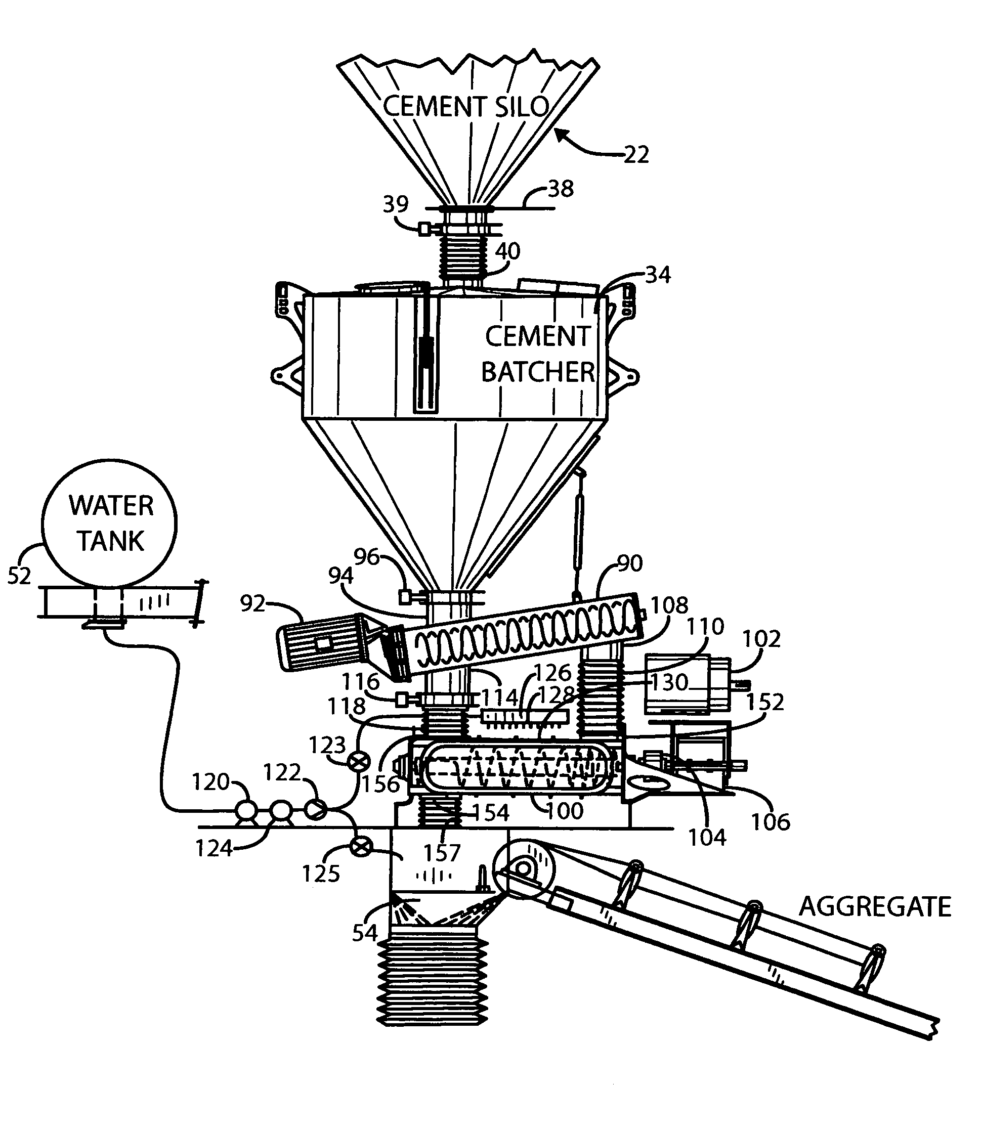
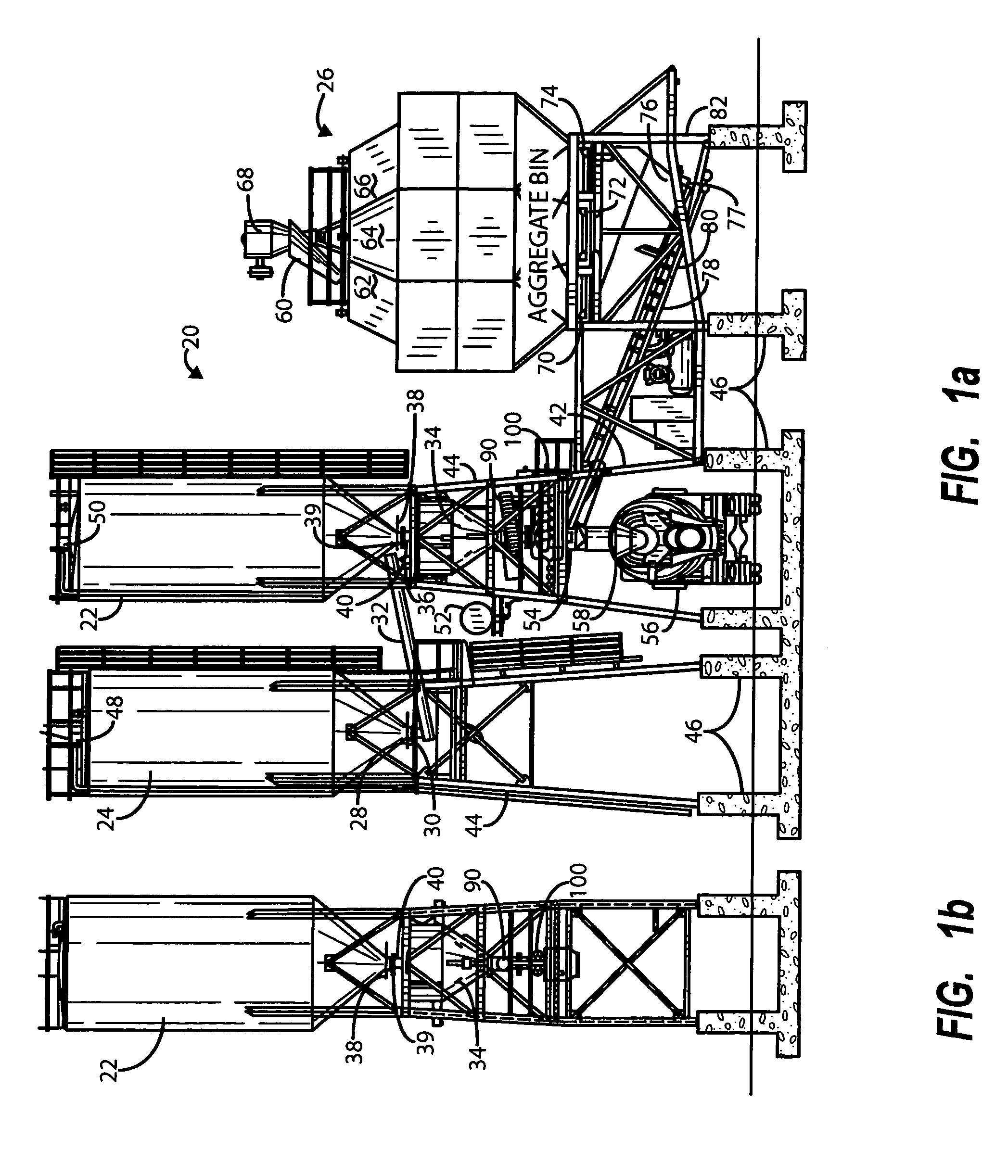
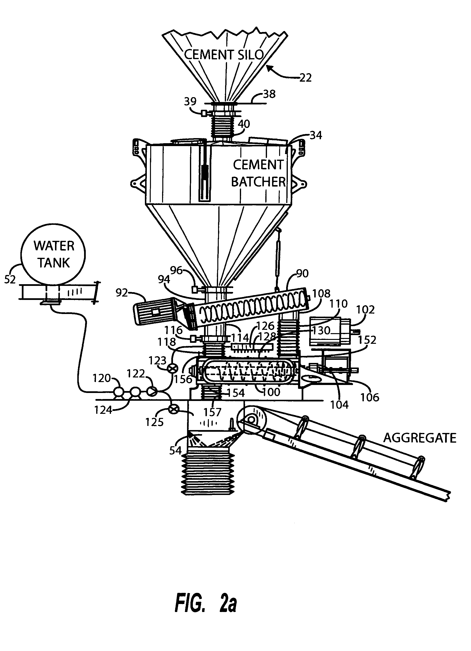
[0045]FIGS. 1a and 1b are elevational views of a portion of a concrete batching facility, generally represented by 20, incorporating an agglomerator-mixer system in accordance with the present invention. The batching facility includes a primary Portland cement silo 22, a second silo 24 which may also contain Portland cement or other finely divided dry cementitious ingredients such as fly ash, which are typically also included in concrete ...


PUM

PropertyMeasurementUnit
feed rateaaaaaaaaaa
feed ratesaaaaaaaaaa
strengthaaaaaaaaaa

Abstract

A concrete batch mixing system and method are disclosed that enable the batch master to measure and control both the water and cementitious ingredient feeds in relation to each other so as to be able to blend the two ingredients in a known, selected, adjustable and repeatable manner, and to agglomerate these ingredients in a counter-rotating twin screw mixing apparatus for use in the preparation of batches of mixed concrete in a concrete batching process.

Description

BACKGROUND OF THE INVENTION[0001]I. Field of the Invention[0002]The present invention relates generally to concrete batching operations and, particularly, to advances in equipment, and in a method of processing or batching the ingredients used to produce concrete mixes. Specifically, this invention encompasses a batching operation that includes a pre-mix system which measures and controls both the water and the cementitious material feeds in relation to each other so as to be able to blend these components in a known, selected, adjustable and repeatable manner that optimizes the water / cement ratio and therefore the production and strength of the concrete mixture for each mix design. The pre-mix system further includes a twin screw agglomerator pre-mixing unit for blending or pre-mixing these materials prior to combining them with aggregates in a drum of a transit mixer truck or other final mixing vessel.[0003]II. Related Art[0004]In a typical concrete batching operation, all the ing...

Claims


Application Information

Patent Timeline
Patent Type & Authority Patents(United States)
IPC IPC(8): B28C7/04B28C7/06B28C7/12B01F7/02B01F7/08B01F15/02B01F15/04B28C5/10B28C5/14B28C7/02B28C7/16
CPCB01F7/022B01F7/082B01F7/085B01F15/0234B01F15/0251B01F15/0445B28C5/146B28C7/02B28C7/0436B28C7/0481B28C7/12B01F27/62B01F27/722B01F27/723B01F35/7173B01F35/71775B01F35/881
Inventor CHRISTENSON, RONALD E.HORTON, ROBERT J.
Owner MCNEILUS TRUCK & MFG INC
Why Eureka
Try Eureka