Chemical filter and fan filter unit having the same

a technology of chemical filters and fan filters, applied in the direction of liquid degasification, auxillary pretreatment, separation processes, etc., can solve the problems of reducing the life of chemical filters, reducing the efficiency of contaminant removal, and increasing the downtime of clean room systems, so as to reduce the time required for chemical filter replacement, reduce the time required for replacement work, and improve the speed of air passing through the filter medium.

Active Publication Date: 2008-01-22
SAMSUNG ELECTRONICS CO LTD
View PDF37 Cites 18 Cited by
  • Summary
  • Abstract
  • Description
  • Claims
  • Application Information

AI Technical Summary

Benefits of technology

[0021]The present invention also provides a fan filter unit including the chemical filter that may be easily replaced.
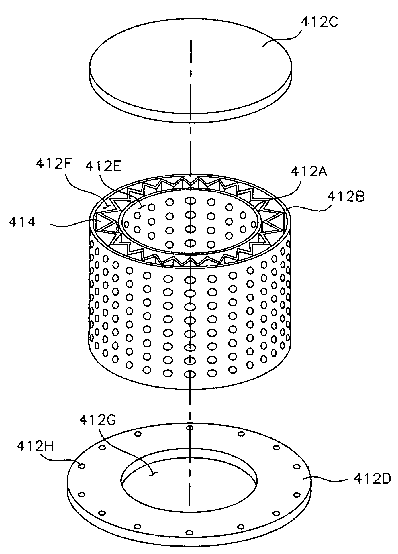
[0023]In an exemplary embodiment of the present invention, the chemical filter may include a first cover removably coupled to top portions of the inner and the outer circular tubes to thereby prevent an air flow through the top portions of the inner and the outer circular tubes, and a second cover detachably attached to bottom portions of the inner and the outer circular tubes. An inner space of the inner circular tube, and an inter-space between the inner and the outer circular tubes may be defined by the first and the second covers. The first cover may have a disc shape and the second cover may have a circular flat ring shape that includes an opening in communication with the inner space of the inner circular tube. The opening may serve as an outlet of the chemical filter.
[0025]In an exemplary embodiment of the present invention, the air, for example, an interior air of ceiling chamber on a clean room, may be sucked into an inner space of the inner circular tube by suction force provided from the fan. The suction force may be provided along a central axis of the inner circular tube, and the inner space of the inner circular tube and an inter-space between the inner and the outer circular tubes may be defined by a first cover removably combined with top portions of the inner and outer circular tubes. Thus, the air may be sucked only through the outer circular tube, the chemical filter and the inner circular tube by the suction force. The inner circular tube may be coaxially arranged within the outer circular tube, and the chemical filter may be coaxially arranged with the fan. Thus, the suction force may be uniformly applied to the inner circular tube, and a velocity distribution of the air passing through the filter medium may be improved. Accordingly, a lifetime of the chemical filter may be increased. In addition, a time required for a replacement work of the chemical filter may be shortened because the chemical filter has a substantially cylindrical shape and is connected to an upper inlet of the fan.
[0026]In accordance with still another aspect of the present invention, there is provided a fan filter unit including a fan, a chemical filter and a particle filter. The fan is provided to suck an air from an interior of a ceiling chamber defining an upper boundary of an interior of a clean chamber and to blow out the air into the interior of the clean room. The fan has an upper inlet for sucking the air and a lower outlet for blowing out the air. The chemical filter is disposed on a top portion of the fan. The chemical filter includes a filter medium for removing chemical contaminants contained in the air being flown into the interior of the clean room, the filter medium having a substantially circular tube shape, an inner circular tube disposed in the filter medium, the inner circular tube having an air-permeability, and an outer circular tube disposed around the filter medium, the outer circular tube having an air-permeability, and a cover removably attached to top portions of the inner and outer circular tubes to prevent an air flow through the top portions of the inner and outer circular tubes into spaces defined by the inner and the outer circular tubes. The upper inlet of the fan is in communication with an inner space of the inner circular tube, and the air is flown only through the outer circular tube, the filter medium and the inner circular tube into the inner space of the inner circular tube. The particle filter is connected to a lower portion of the fan to remove particles contained in the air blown out by the fan.

Problems solved by technology

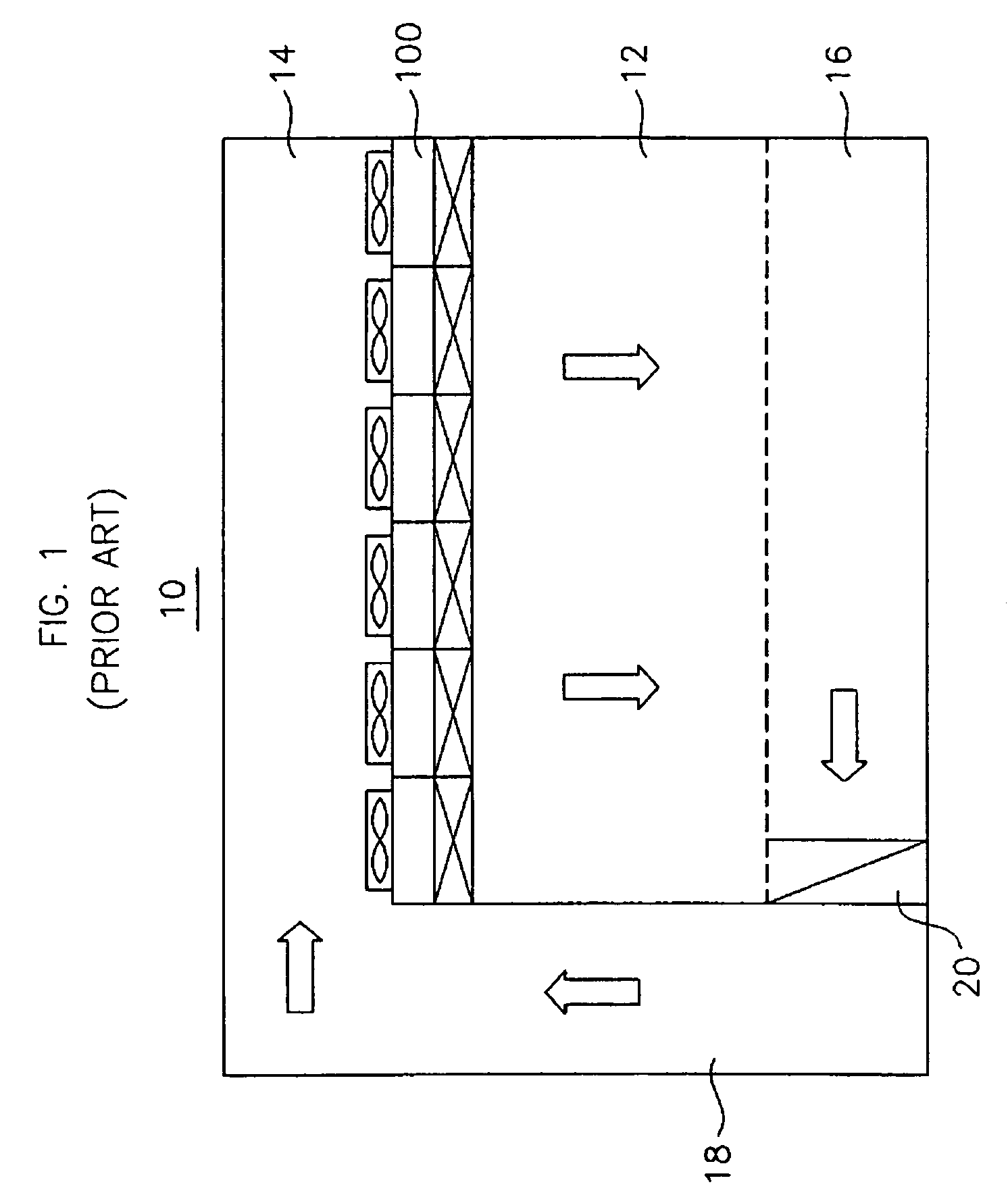
That is, because an air flow rate in the edge portion is greater than that in the central portion, an adsorption rate of the edge portion is substantially higher than that of the central portion so that a contaminant removal efficiency may be deteriorated in the edge portion.
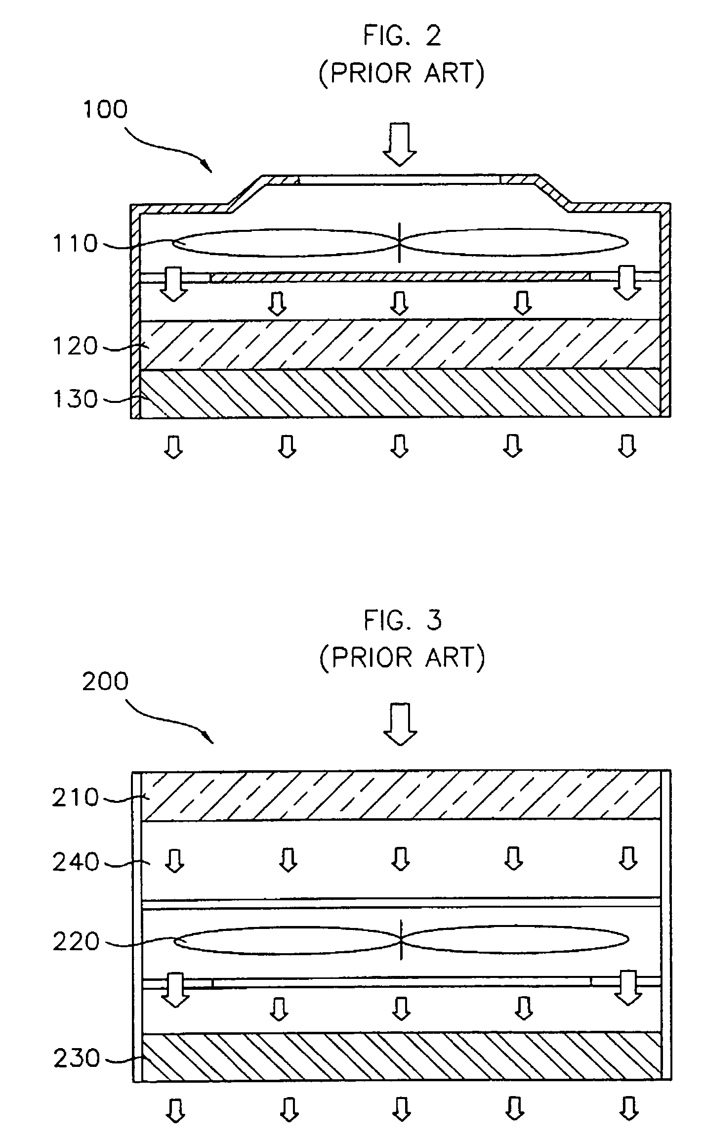
In addition, the time required may be increased because it is not ease to secure a sufficient working space, and a downtime of the clean room system may be increased because operation of the fan 110 or 220 is interrupted during a replacement work.
However, there is a problem that a velocity distribution of the air passing through the chemical filter 310 is not uniform because an air velocity difference between an upper portion and side portions of the chemical filter 310.

Method used


Image

  • Chemical filter and fan filter unit having the same
  • Chemical filter and fan filter unit having the same
  • Chemical filter and fan filter unit having the same

Examples


Embodiment Construction

[0037]The invention now will be described more fully hereinafter with reference to the accompanying drawings, in which embodiments of the invention are shown. This invention may, however, be embodied in many different forms and should not be construed as limited to the embodiments set forth herein. Rather, these embodiments are provided so that this disclosure will be thorough and complete, and will fully convey the scope of the invention to those skilled in the art. Like numbers refer to like elements throughout.

[0038]It will be understood that when an element is referred to as being “on” another element, it can be directly on the other element or intervening elements may be present. In contrast, when an element is referred to as being “directly on” another element, there are no intervening elements present. As used herein, the term “and / or” includes any and all combinations of one or more of the associated listed items.

[0039]It will be understood that, although the terms first, se...


PUM

PropertyMeasurementUnit
air velocityaaaaaaaaaa
velocity deviationaaaaaaaaaa

Abstract

In a fan filter unit for filtering and continuously supplying clean air into a clean room, the fan filter unit includes a chemical filter for removing chemical contaminants contained in the air, a fan for sucking and blowing out the air, and a particle filter for removing particles such as dusts and moisture contained in the air. A filter medium of the chemical filter has a circular tube shape and is disposed between an inner circular tube and an outer circular tube. A cover is detachably combined with top portions of the inner and the outer circular tubes, and prevents air flow through the top portions of the inner and outer circular tubes. The air is sucked only through the outer circular tube, the chemical filter and the inner circular tube by a suction force of the fan. Accordingly, velocity distribution of the air passing through the chemical filter may be improved and lifetime of the chemical filter may be increased.

Description

BACKGROUND OF THE INVENTION[0001]1. Field of the Invention[0002]The present invention relates to a chemical filter for removing chemical contaminants contained in an air supplied into a clean space and a fan filter unit having the same. More particularly, the present invention relates to a chemical filter for removing chemical contaminants contained in an air supplied into a clean room in which semiconductor device manufacturing processes are carried out, and a fan filter unit having the chemical filter.[0003]2. Description of the Related Art[0004]Semiconductor devices are generally manufactured through several manufacturing processes such as a fabrication process, an electrical die sorting (EDS) process, a packaging process, etc.[0005]In the fabrication process, electronic circuits may be formed on a semiconductor substrate such as a silicon wafer. The EDS process may be carried out for inspecting electrical characteristics of elements and / or semiconductor devices formed on the sem...

Claims


Application Information

Patent Timeline
Patent Type & Authority Patents(United States)
IPC IPC(8): B01D46/00
CPCB01D46/10B01D46/2411B01D53/0415B01D53/0446B01D2257/106B01D2257/406B01D2257/80B01D2258/0216B01D2259/4508B01D2279/51
Inventor HAM, DONG-SEOKLEE, HOO-KUN
Owner SAMSUNG ELECTRONICS CO LTD
Why Eureka
Try Eureka