Multi pole electrical machine with reduced cogging force

a technology of cogging force and electrical machine, which is applied in the direction of synchronous machines with stationary armatures, windings, windings, etc., can solve the problems of uneven running, unfavorable cogging force generation, and the necessity of adhering to minimum speed, so as to achieve good efficiency of the new electrical machine

Inactive Publication Date: 2008-01-22
INVACARE CORP +1
View PDF21 Cites 13 Cited by
  • Summary
  • Abstract
  • Description
  • Claims
  • Application Information

AI Technical Summary

Benefits of technology

[0018]The connection scheme for the sub-arrangement of stator poles or the stator pole segments, respectively, in parallel connection or series connection or in a combination of these two combinations allows a variation of the connecting values of the new electrical machine with regard to their operating voltage and their operating current, i.e. their supply impedance, without the necessity for a use of

Problems solved by technology

In this way the disadvantageous cogging force is generated, which is particularly typical for slow idle motion.
The results are uneven running, the necessity of adhering to minimum speed, undesired noise, vibrations etc.
It turns out, however, that this approach is very costly and that it usually has a negative impact on the efficiency of the electrical machine.
The disadvantage here is that the actual described three-phase electrical machine can only be used for a very narrow range of operation parameters.
Furthermore, the non-equidistant arrangement of the armature poles excludes the use of the so-called Hall element-effect devices as rotor position detectors, which is very common in electronically commuted machines, because the non-equidistant arrangement of the armature poles causes a big angular jitter during the position detection of the armature field.
However, especially in case of a high number of poles, it turns out that the averaging of the cogging forces put on the poles no longer completely occurs, because mechanical deformations of the armature or the stator, which may be caused by manufacture or load, or interferences in the equidistance of the armature poles or an eccentricity of the stator or the r

Method used


Image

  • Multi pole electrical machine with reduced cogging force
  • Multi pole electrical machine with reduced cogging force
  • Multi pole electrical machine with reduced cogging force

Examples


Embodiment Construction

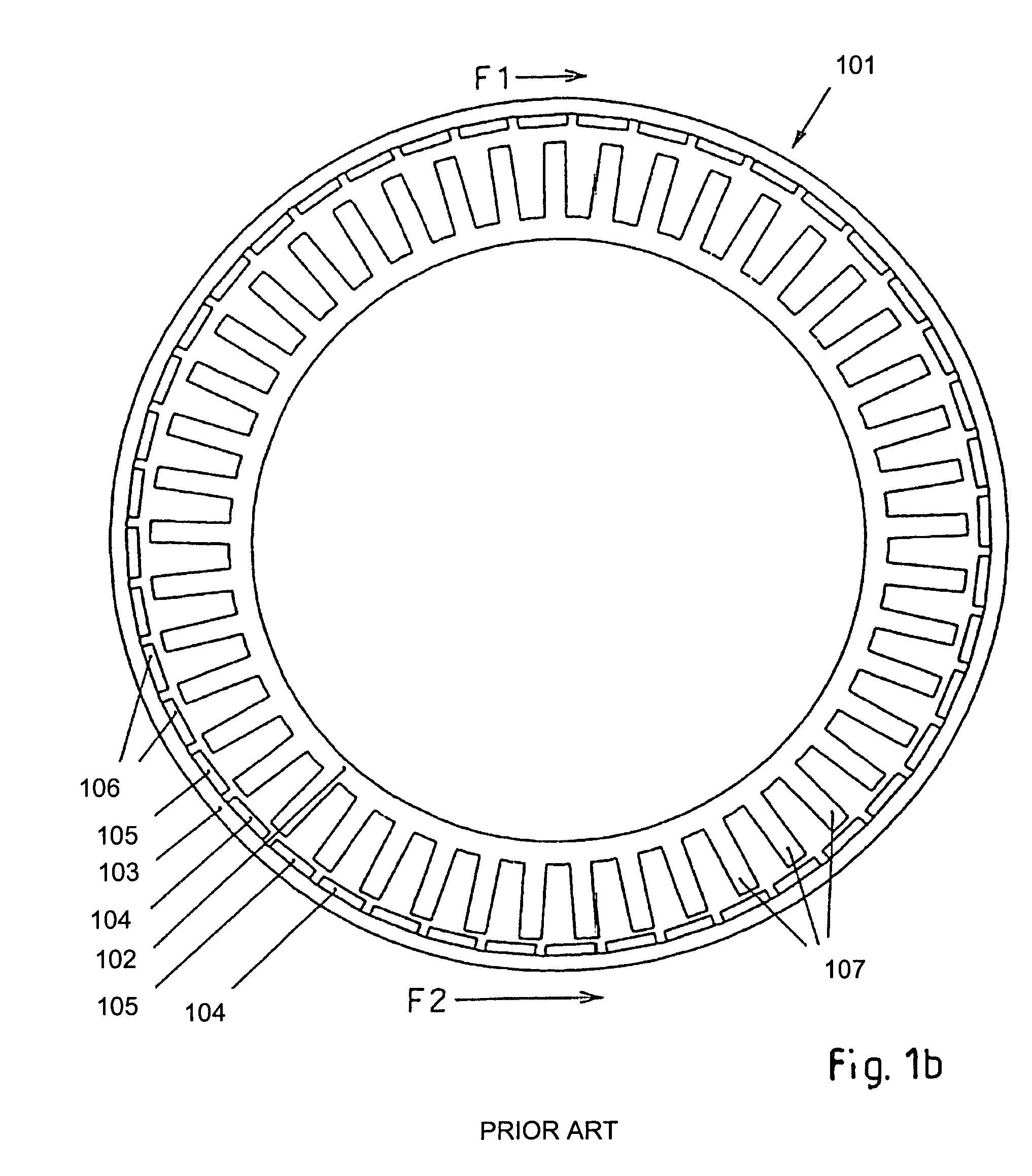
[0036]FIGS. 1a and 1b illustrate a state of the art electrical machine 101 which is constructed as a rotary machine. The electrical machine 101 has an internal stator 102 and an external armature 103 which surrounds the stator 102 and which can also be called rotor in this case of a rotary machine. Armature 103 is permanently excited by means of permanent magnets 106. In this present case, armature 103 has an armature pole arrangement, in which magnetic south poles 104 and magnetic north poles 105 alternate and in which each time one south pole 104 and one north pole 105 form one armature pole pair 104, 105 corresponding to an entire magnetic period. Stator 102 of electrical machine 101 is designed for a three-phase electrical machine in a three-phase network with the phases U, V and W. The stator poles 107 are marked accordingly in the same way as in EP 0 291 219 A1, which is incorporated by references here. That means the stator poles 107 designated A1, A3, A5 etc. correspond to c...


PUM


Abstract

A multi pole electrical machine includes an armature and a stator. The armature is movable in a direction of armature motion with regard to said stator and includes armature pole pairs. These armature pole pairs follow each other in the direction of armature motion. Each armature pole pair corresponds to one magnetic period. The stator includes a differing fixed number of stator poles per armature pole pair to reduce a cogging force of the electrical machine. An arrangement of the stator poles, with regard to both electrical and magnetic aspects, includes at least two identical sub-arrangements of stator poles. These sub-arrangements of stator poles follow each other in the direction of armature motion. Each of the sub-arrangements of stator poles is associated with one or more armature pole pairs and includes more than three of stator poles.

Description

CROSS REFERENCES TO RELATED APPLICATIONS[0001]This patent application is a continuation of application Ser. No. 09 / 553,522, filed Apr. 20, 2000, now abandoned and titled “Multi Pole Electrical Machine With Reduced Cogging Force.”FIELD OF THE INVENTION[0002]This invention relates in general to multi pole electrical machines with reduced cogging torque. More particularly, this invention relates to multi pole electrical machines, the electrical machines including an armature and a stator; said armature being movable in a direction of armature motion with regard to said stator, said armature including an integer number of armature pole pairs, said armature pole pairs following each other in the direction of armature motion, and each of said armature pole pairs corresponding to one magnetic period; said stator including a fixed number of stator poles per armature pole pair, the number of stator poles per armature pole pair differing from an integer number to reduce a cogging force of the...

Claims


Application Information

Patent Timeline
IPC IPC(8): H02K21/12H02K1/14H02K29/03
CPCH02K1/146H02K1/148H02K29/03
Inventor STROTHMANN, THOMAS
Owner INVACARE CORP
Why Eureka
Try Eureka