Turbine motor of a rotary atomizer

a technology of rotary atomizer and turbine motor, which is applied in the direction of machines/engines, liquid fuel engines, lighting and heating apparatus, etc., can solve the problems of limited efficiency of known radial turbines and high friction losses, and achieves improved driving efficiency of turbines, low friction, and high rpm.

Active Publication Date: 2008-01-29
DURR SYST INC
View PDF38 Cites 12 Cited by
  • Summary
  • Abstract
  • Description
  • Claims
  • Application Information

AI Technical Summary

Benefits of technology

[0006]The turbine is significantly improved by the invention in terms of flow. In particular, because the drive channel is not limited on only one side as before, but instead is also closed on the other side by an element that rotates with the turbine, the drive air can flow through the closed channel without losses and with low friction. An advantageous possibility for realization is to limit the drive channel by a disk, which is attached to the turbine wheel and/or to the drive shaft, which rotates with the wheel, and which can form or contain at least one outlet opening for the driving air on the inside in the radial direction.
[0007]According to another feature of the invention, the cross-sectional area of the inlet opening through which the driving air flows from a supply channel of the bearing unit into the drive channel of the turbi

Problems solved by technology

Another disadvantage is a turbulent boundary layer, which forms between the flowing driving air and the stationary housing part for th

Method used


Image

  • Turbine motor of a rotary atomizer
  • Turbine motor of a rotary atomizer

Examples


Embodiment Construction

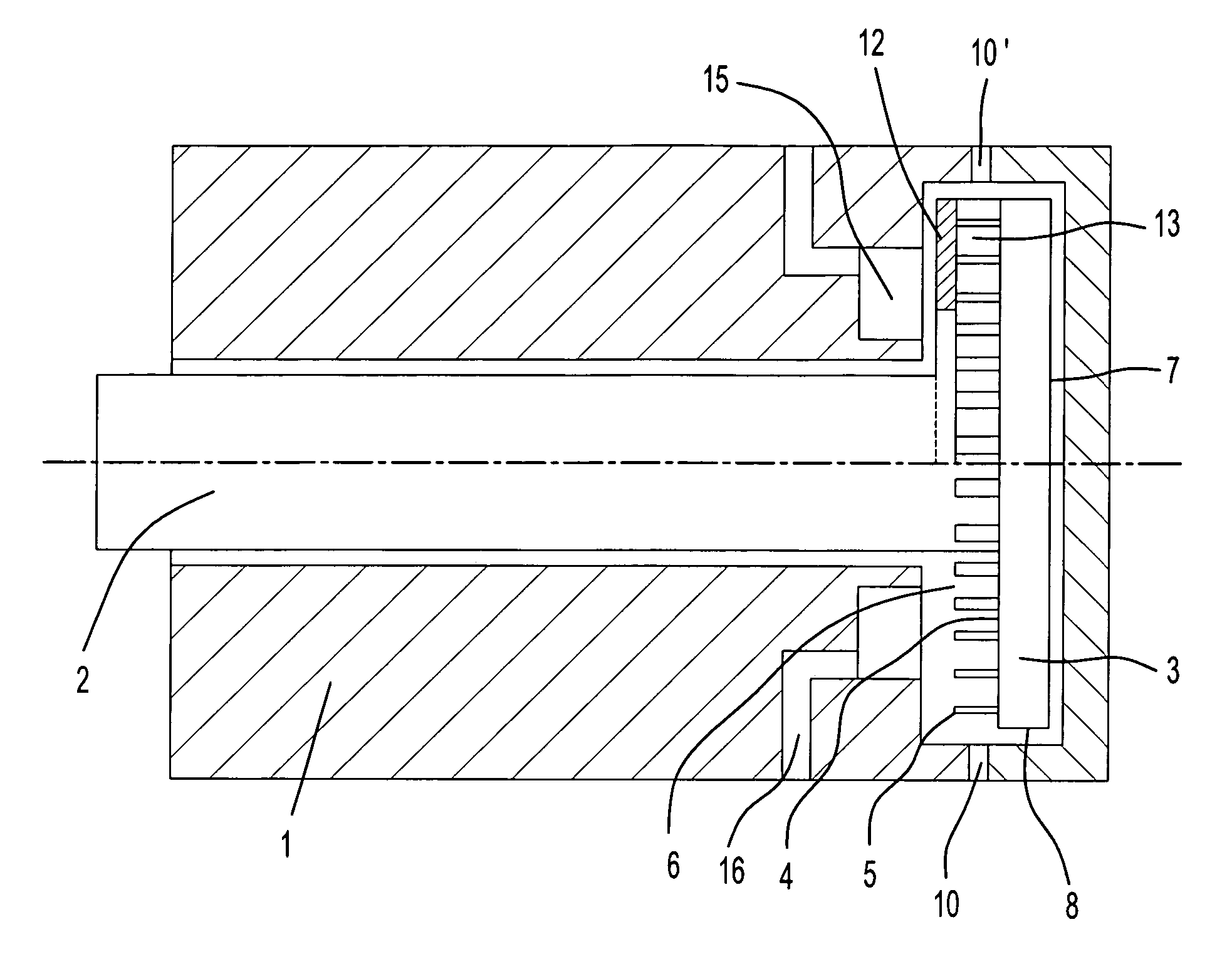
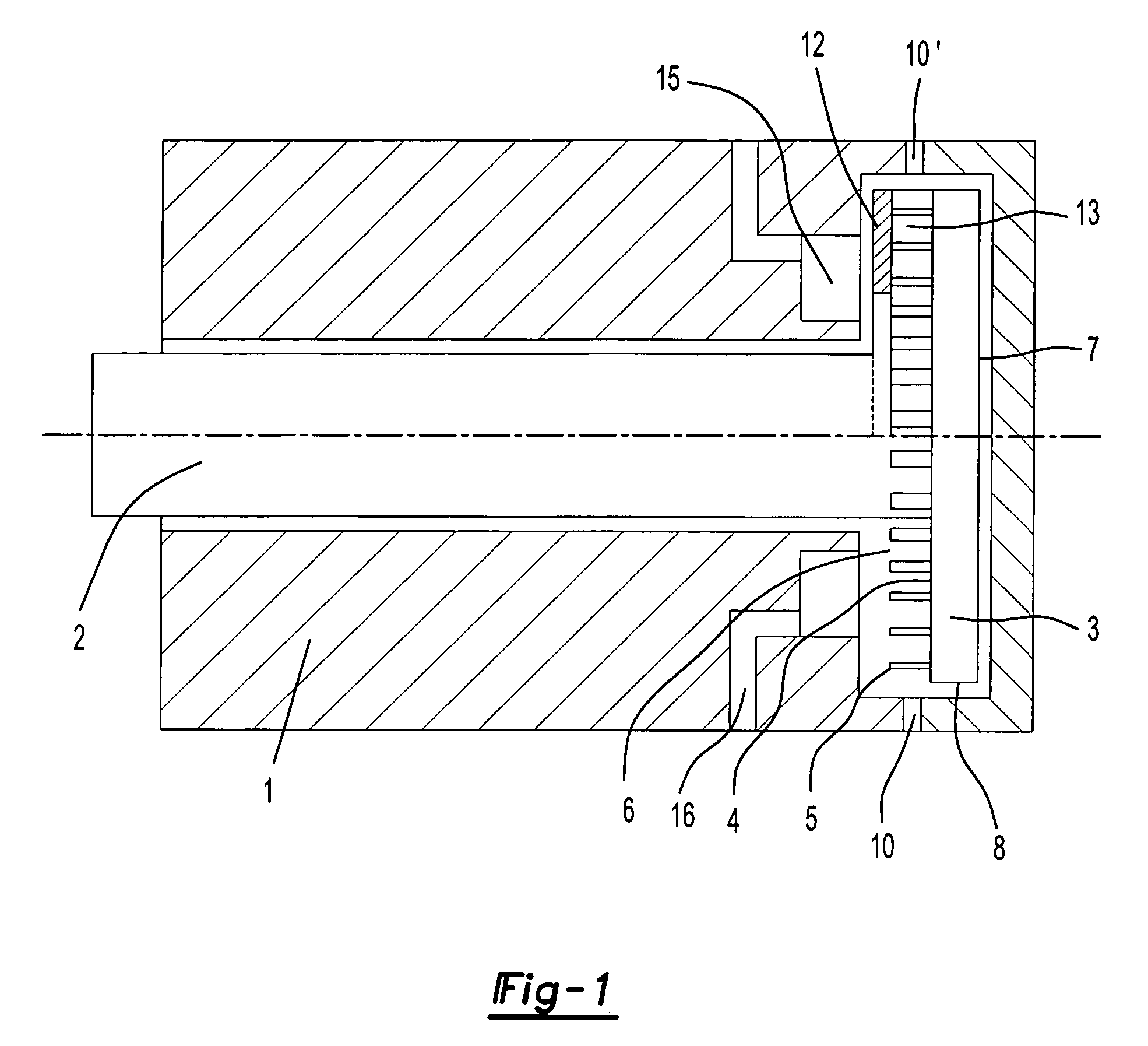
[0012]The bearing unit forming the turbine motor described here has a stationary housing 1, in which the drive shaft 2 rotates in an air bearing formed between the housing and the shaft. The disk-shaped turbine wheel 3 is arranged at one end of the drive shaft 2. The ring of turbine blades 5 for flow in the radial direction is formed on an annular area of the axial end surface 4 of the turbine wheel facing the shaft lying near the periphery of the disk. The turbine wheel 3 rotates in a cylindrical interior 6 of the housing 1 dimensioned corresponding to the turbine wheel with walls adjacent to the rear flat end surface 7 and the cylindrical peripheral surface 8 of the turbine wheel. On the opposite side, on the left in the drawing, the interior 6 is limited by another wall surface of the stationary housing 1 running in the radial direction, which forms the opening for the shaft 2 in the center and which is positioned, outside of this opening, opposite the axial end surface 4 of the ...


PUM


Abstract

A turbine, e.g., with a blade arrangement, which receives an air flow in the radial direction and which is located on a carrier surface of the turbine wheel, is used as a drive motor for a rotary atomizer. The drive channel, which contains the turbine blades and which is limited by the carrier surface, is also closed on its other side by a cover element, which is attached to the turbine wheel and which rotates with the wheel for increasing efficiency. For an additional increase in efficiency, the inlet for the drive air of the turbine is configured as an ultrasonic nozzle with a cross section that expands continuously up to the opening.

Description

PRIOR APPLICATIONS[0001]This application claims priority to German Patent Application No. DE 102 33 199.5 filed Jul. 22, 2002.FIELD OF THE INVENTION[0002]The invention concerns a turbine motor that can be used as the drive for the bell-shaped Plate of a rotary atomizer according to the preamble of claim 1. More specifically, it concerns high-speed rotary atomizers for the electrostatic mass-production coating of workpieces, such as vehicle chassis.BACKGROUND[0003]Radial turbines, which are operated in a known way with compressed air and which have a hollow shaft that carries the bell-shaped plate and that rotates in an air bearing, are used for driving the bell-shaped plate of such atomizers (DE 43 06 80, EP 0 796 663 B1). Air can either flow against the radial turbines in the tangential direction or through the turbines in the radial direction. In the latter case, the turbine wheel consists of a disk, which rotates in an essentially closed cylindrical interior of the bearing unit o...

Claims


Application Information

Patent Timeline
IPC IPC(8): F01D1/08B05B3/10B05B5/04F01D1/22F01D15/00F01D15/06F02C1/00
CPCB05B3/1035B05B5/0415F01D1/22F01D15/00F01D15/065F02C1/00Y02T50/60
Inventor BAUMANN, MICHAELHERRE, FRANKNOLTE, HANS J.KRUMMA, HARRYGIULIANO, STEFANOLIND, BJORN
Owner DURR SYST INC
Why Eureka
Try Eureka