Oil feeding device

a technology of oil feeding device and oil feed, which is applied in the direction of electric propulsion mounting, machine/engine, etc., can solve the problems of reducing lubricating performance and cooling performance, rotary elements are worn away, etc., and achieve the effect of suppressing the reduction of oil fed

Active Publication Date: 2008-01-29
TOYOTA JIDOSHA KK
View PDF23 Cites 20 Cited by
  • Summary
  • Abstract
  • Description
  • Claims
  • Application Information

AI Technical Summary

Benefits of technology

[0009]An object of this invention is to provide an oil feeding device capable of suppressing a reduction of an amount of oil fed to an oil requiring portion, even when a velocity of the moving object changes.
[0019]According to the present invention, when an inertia force is generated in the moving direction of the moving object as a result of the acceleration or deceleration, the oil discharged from the first oil discharging portion contacts with the regulating member. The oil discharged from the first oil discharging portion contacts with the regulating member, also in case the moving object leans in the moving direction on an upslope or a downslope. Therefore, it is possible to suppress the increase in a relative travel distance between the oil discharged from the first oil discharging portion and the oil requiring portion, and to suppress the reduction of the amount of oil at the first oil requiring portion.
[0021]In addition to the above-mentioned effects, according to the present invention, the oil discharged from the first oil discharging portion is fed though a plurality of oil passages to the first oil requiring portion. Accordingly, even if the amount of oil fed though any one of the oil passages to the first oil requiring portion decreases, the oil is fed to the first oil requiring portion through other oil passages. Therefore, the reduction in the amount of oil at the first oil requiring portion can be suppressed more certainly.

Problems solved by technology

In a power transmission system mounted on a moving object, heat is generated on rotary elements forming a part of the power transmission system, and those rotary elements are worn away.
Therefore, the oil runs short at the meshing portion of the gears, and this may degrade a lubricating performance and a cooling performance.

Method used


Image

  • Oil feeding device
  • Oil feeding device
  • Oil feeding device

Examples


Embodiment Construction

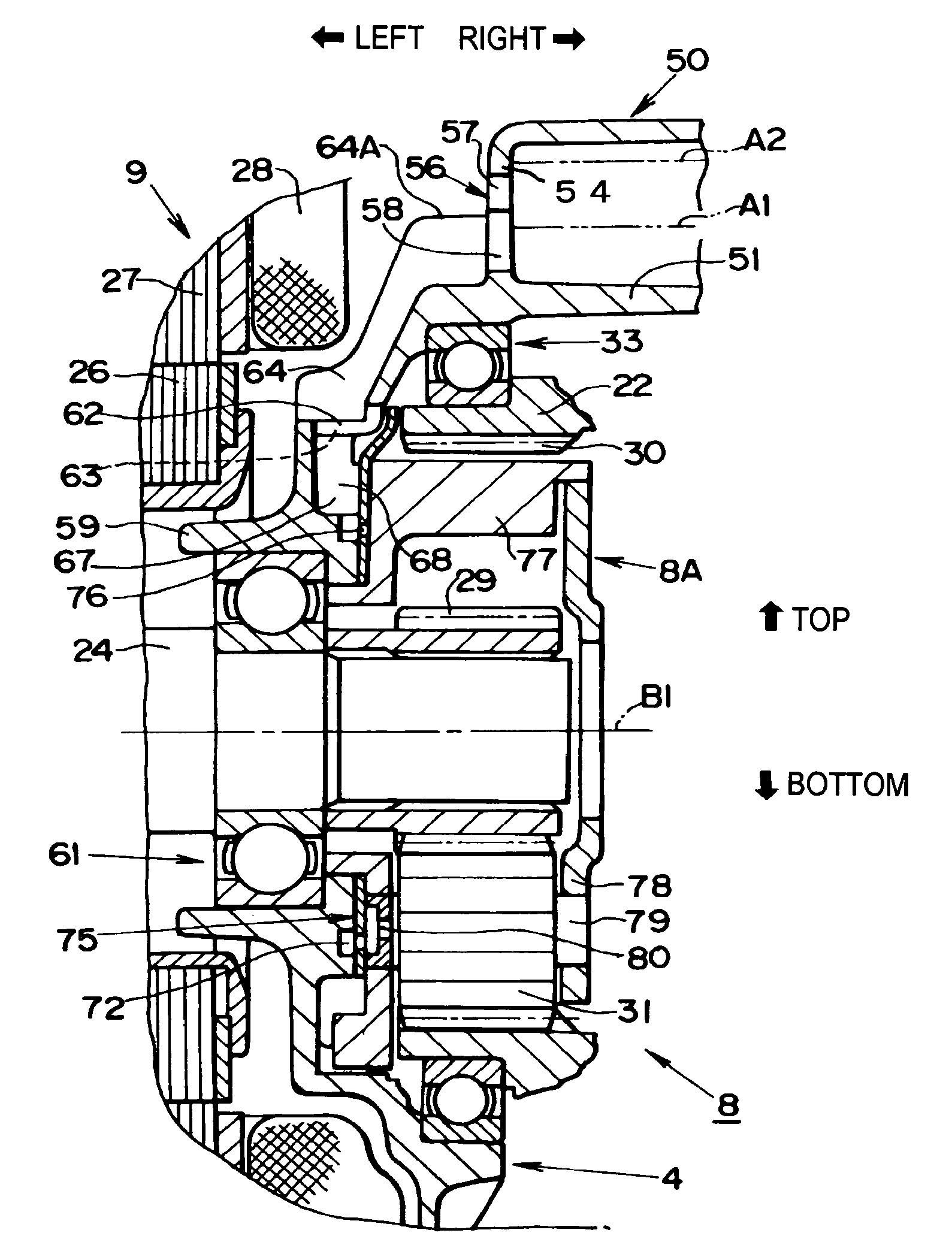
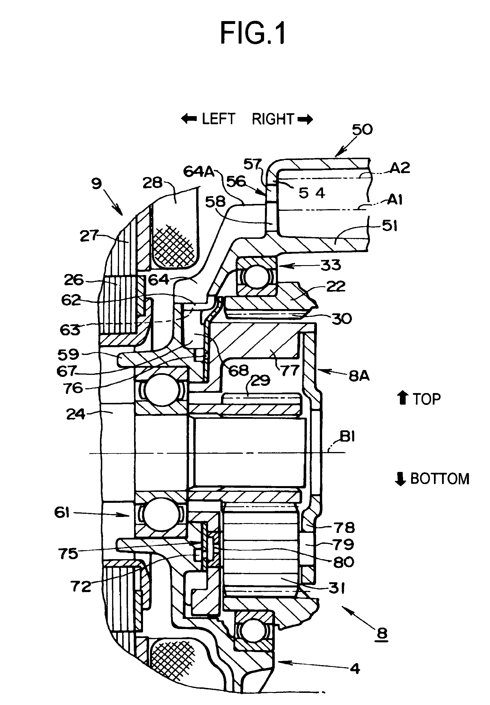
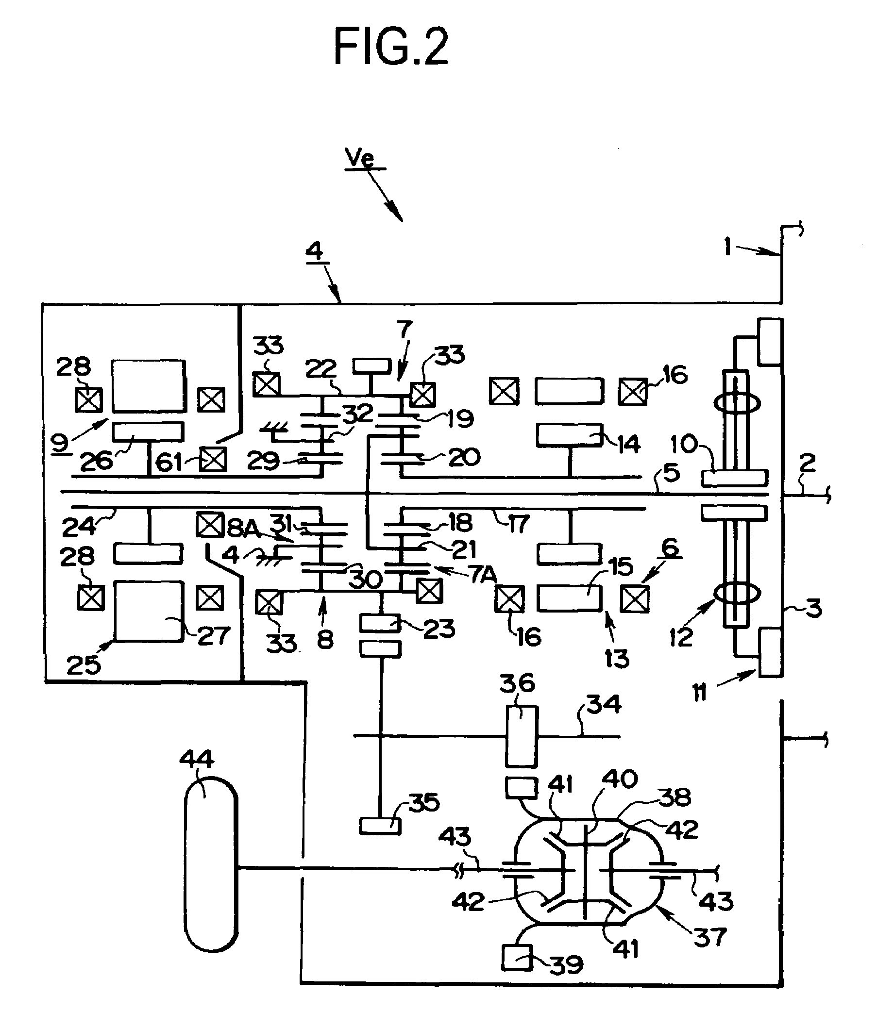
[0030]Next, a specific embodiment of this invention will be described hereinafter. The moving object to which the invention is applied is, e.g., a vehicle in which a prime mover is provided and a power of the prime mover is transmitted through a power transmission system to wheels. A gear transmission device or a belt transmission device is used for the power transmission system (i.e., a transmission device). Specifically, those transmission devices comprise such elements as gears meshing with each other, a belt and a pulley, a bearing for holding a rotary member or the like, and a sliding movement, a heat generation and an abrasion occur in those elements. Therefore, the aforementioned elements, i.e., the oil requiring portions are lubricated and cooled by oil fed from the oil feeding device. Hereinafter, an embodiment of the case in which the oil feeding device is employed as the device for lubricating and cooling the power transmission system of a vehicle will be described.

[0031]...


PUM


Abstract

An oil feeding device which has an oil reserving portion 50 and first oil requiring portions 8, 62, 63, 67, 68, 72 and 76 provided in a moving object, and a first oil discharging portion 58 for feeding an oil reserved in the oil reserving portion 50 to the first oil requiring portions comprises: a regulating member 64 for regulating a relative movement of the oil discharged from the first oil discharging portion 58 and the first oil requiring portions in a moving direction of the moving object; a second oil discharging portion 57 for feeding the oil reserved in the oil reserving portion 50 to the first oil requiring portions. A discharging pressures of the oil at the first oil discharging portion 57 and the second oil discharging portion 58 are changed in accordance with the amount of the oil in the oil reserving portion 50. Therefore, the reduction of the amount of oil to be fed to the first oil requiring portions can be suppressed even when the speed of the moving object changes.

Description

BACKGROUND OF THE INVENTION[0001]1. Field of the Invention[0002]This invention relates to an oil feeding device for feeding oil to an oil requiring portion.[0003]The disclosure of Japanese Patent Application No. 2003-3 56811 filed on Oct. 16, 2003 including specification, drawings and claims is incorporated herein by reference in its entirety.[0004]2. Description of Related Art[0005]In a power transmission system mounted on a moving object, heat is generated on rotary elements forming a part of the power transmission system, and those rotary elements are worn away. In the prior art, therefore, oil is fed to cool and lubricate where the heat is generated or where to be worn. There are known two kinds of method for feeding oil to the heating portion or wearing portion of the power transmission system. The first oil feeding method is a so-called scraping method, in which oil is fed to the oil requiring portion by scraping up the oil in an oil reservoir by the rotary elements constituti...

Claims


Application Information

Patent Timeline
Patent Type & Authority Patents(United States)
IPC IPC(8): F16H57/04F16H3/72B60K1/02B60L50/16
CPCB60K6/405B60K6/445B60K1/02B60W2520/105Y10T74/19991F16H57/045F16H57/0476F16H57/0484Y02T10/6239F16H57/0424Y02T10/62F16H61/4165
Inventor ICHIOKA, EIJIWATANABE, HIDETO
Owner TOYOTA JIDOSHA KK
Why Eureka
Try Eureka