Method and apparatus to improve ADC dynamic range in a video decoder

a dynamic range and video decoder technology, applied in the field of video decoders, can solve the problems of the resolution of any analog-to-digital converter which is utilized, and achieve the effects of improving resolution quality, improving resolution quality, and reducing bit coun

Inactive Publication Date: 2008-01-29
CIRRUS LOGIC INC
View PDF7 Cites 4 Cited by
  • Summary
  • Abstract
  • Description
  • Claims
  • Application Information

AI Technical Summary

Benefits of technology

[0006]In a video decoder according to the present invention, 1) resolution quality can be improved for a given bit count analog-to-digital converter, 2) a lower bit count analog-to-digital converter can be used with substantially similar quality or 3) a combination of improved resolution quality with a lower bit count analog-to-digital converter can be done. In the preferred embodiment a DC bias is added to the video signal after the sync portion of the composite signal has been received and prior to the active video being received. This bias is then removed after the end of the active video period. By applying this bias, the DC voltage level of the video signals is actually reduced, so that the full scale value of the analog-to-digital conversion process can also be reduced. Thus, compared to using an unbiased signal, increased A / D converter resolution is obtained.

Problems solved by technology

The decoder not only has to handle composite signals, which means it must be able to determine the chroma and luma values, but it also must handle vertical blanking interval (VBI) data and handle VCR signals, which may be unstable signals.
For example, one common problem is resolution of any analog-to-digital converters which are utilized.

Method used


Image

  • Method and apparatus to improve ADC dynamic range in a video decoder
  • Method and apparatus to improve ADC dynamic range in a video decoder
  • Method and apparatus to improve ADC dynamic range in a video decoder

Examples


Embodiment Construction

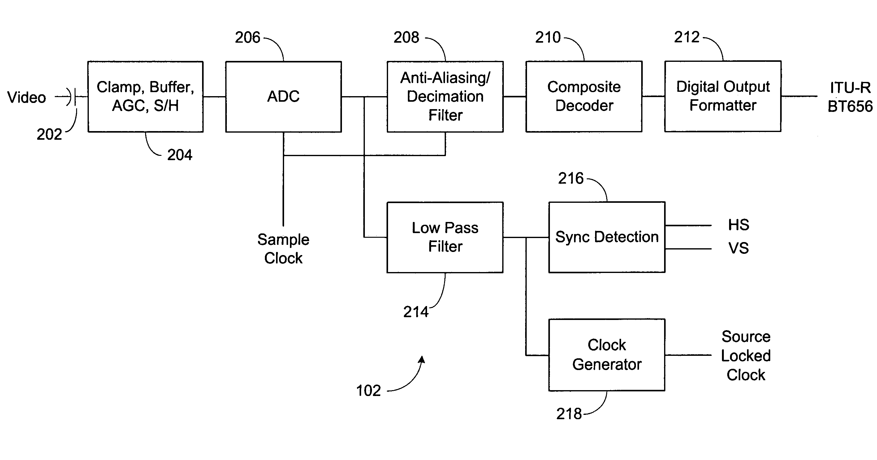
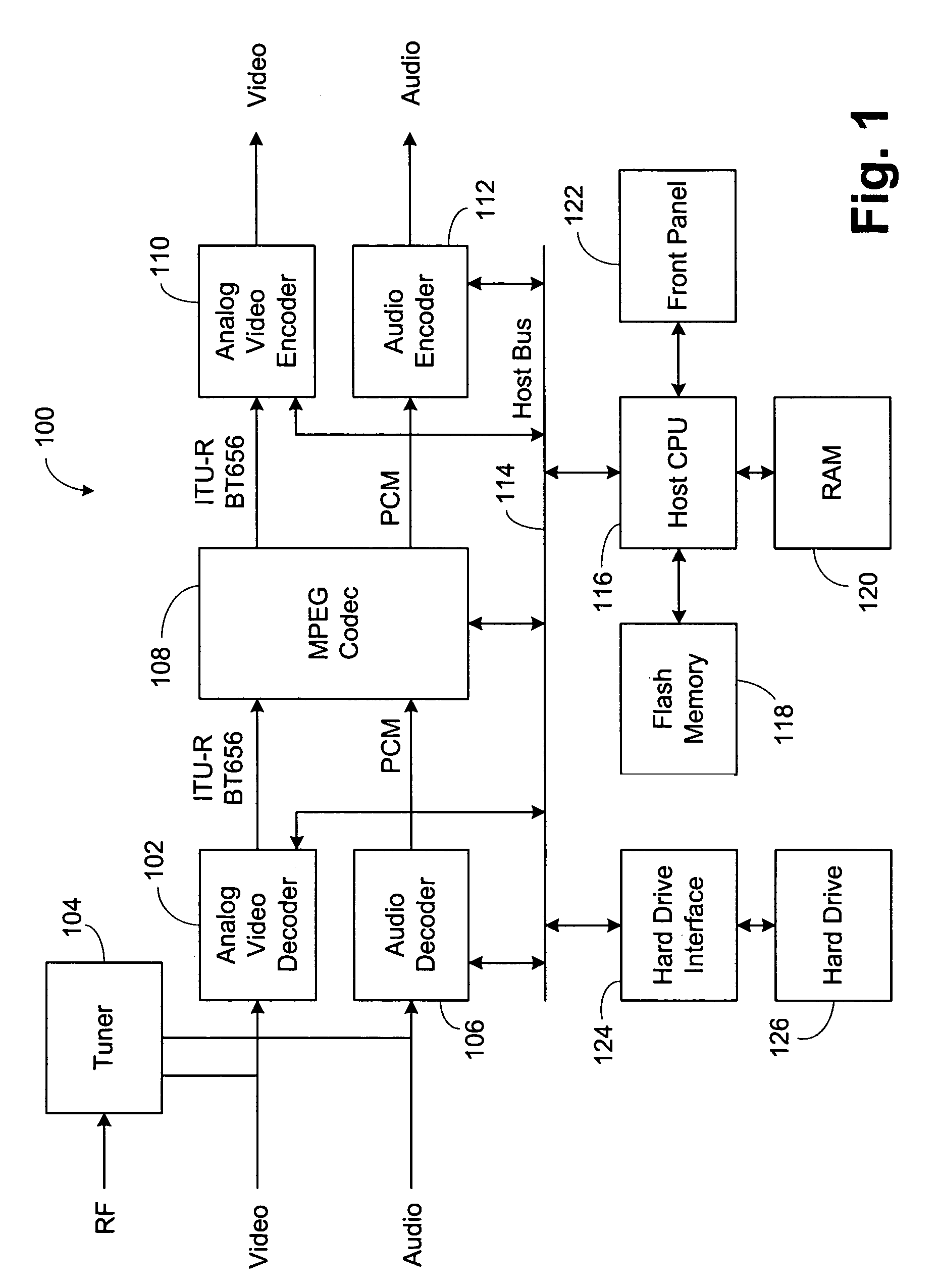
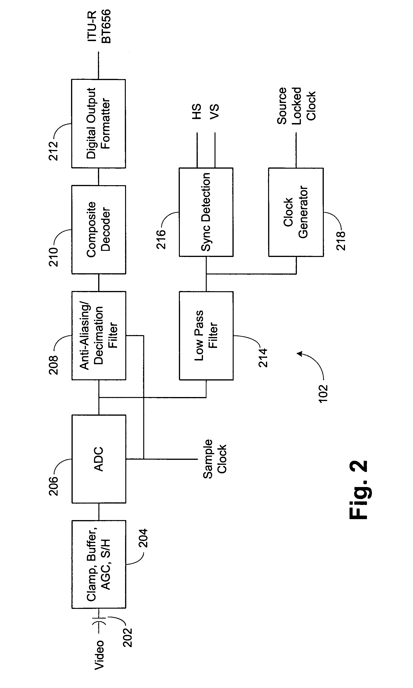
[0015]Referring now to FIG. 1, an exemplary personal video recorder (PVR) 100 is shown. This is an exemplary use of analog video decoder 102, and it is understood that the analog video decoder can be used in multiple applications including digital televisions, LCD (Liquid Crystal Display) TVs, DVD (Digital Versatile Disc) recorders, video capture situations, and the like. A radio frequency or broadcast signal is provided to a tuner 104. The tuner 104 provides both video and audio outputs. The video output from the tuner 104 or a video signal from an external connection is provided to analog video decoder 102. The audio signal from the tuner 104 or an external audio signal is provided to an audio decoder 106. The output in the analog video decoder 102 is preferably an ITU-R (International Telecommunication Union—Radio—Communication) BT (Broadcasting Service—television) 656 format digital signal, which is either an eight or ten bit signal. This output of analog video decoder 102 is pr...


PUM


Abstract

A video decoder in which 1) resolution quality can be improved for a given bit count analog-to-digital converter, 2) a lower bit count analog-to-digital converter can be used with substantially similar quality or 3) a combination of improved resolution quality with a lower bit count analog-to-digital converter can be done. In the preferred embodiment, a DC bias is added to the video signal after the sync portion of the composite signal has been received and prior to the active video being received. This bias is then removed after the end of the active video period. By applying this bias, the DC voltage level of the video signals is actually reduced, so that the full scale value of the analog-to-digital conversion process can also be reduced. Thus, compared to using an unbiased signal, increased A / D converter resolution is obtained. In an alternative embodiment, the sync portion can be biased upwardly during the front porch and then be returned during the back porch.

Description

BACKGROUND OF THE INVENTION[0001]1. Field of the Inventions[0002]The inventions generally relates to video decoders, and more specifically to input video signal shaping, and even more specifically to providing constant video signal levels and improving analog-to-digital conversion accuracy.[0003]2. Description of Related Art[0004]There is a large surge in the use of digital video devices today. Examples include: digital televisions, LCD TVs and monitors, DVD recorders, personal video recorders, PC video cards, video capture and streaming applications, and video conferencing. In many cases, these units need to receive an analog video signal, which may be one of the composite signals, such as NTSC, PAL or SECAM; s-video; component video or RGB. It is then desirable to produce the proper digital output, such as eight or ten bit ITU-R BT 656. It is preferred that all the video decoding be done in a single chip for all of these formats. The decoder not only has to handle composite signal...

Claims


Application Information

Patent Timeline
Patent Type & Authority Patents(United States)
IPC IPC(8): H03M1/12
CPCH04N5/18H03M1/129
Inventor GUDMONDSON, DANIELSOMAYAJULA, SHYAM
Owner CIRRUS LOGIC INC
Why Eureka
Try Eureka