
Spectral encoder

a spectral encoder and encoder technology, applied in the field of spectral encoders, can solve the problems of difficult two-dimensional imaging approaches and poor image quality, and achieve the effects of reducing image aberration, improving overall image quality, and high-quality two-dimensional images

Active Publication Date: 2008-01-29
GOLDSTEIN NEIL +6
View PDF13 Cites 16 Cited by
  • Summary
  • Abstract
  • Description
  • Claims
  • Application Information

AI Technical Summary

Benefits of technology

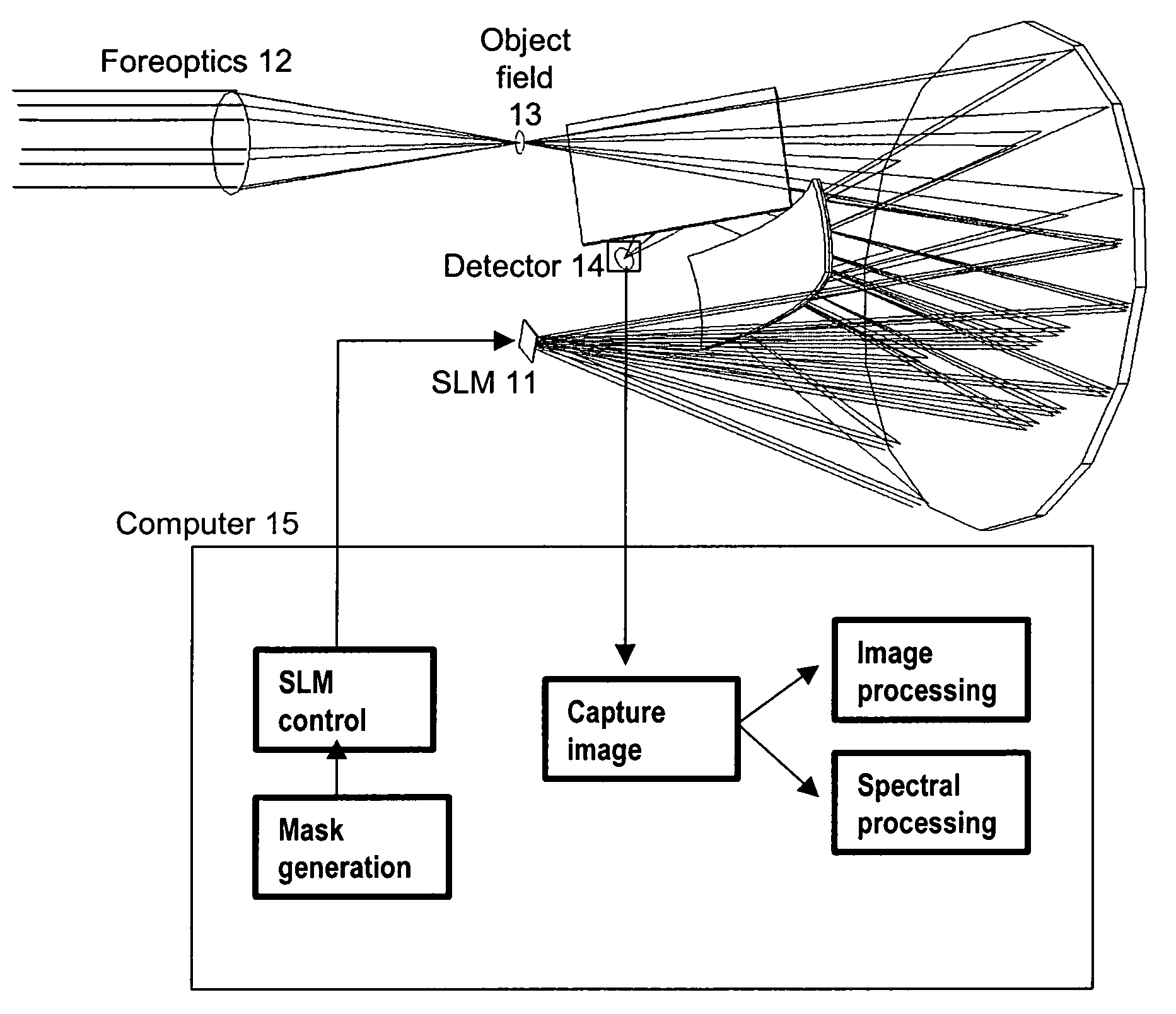
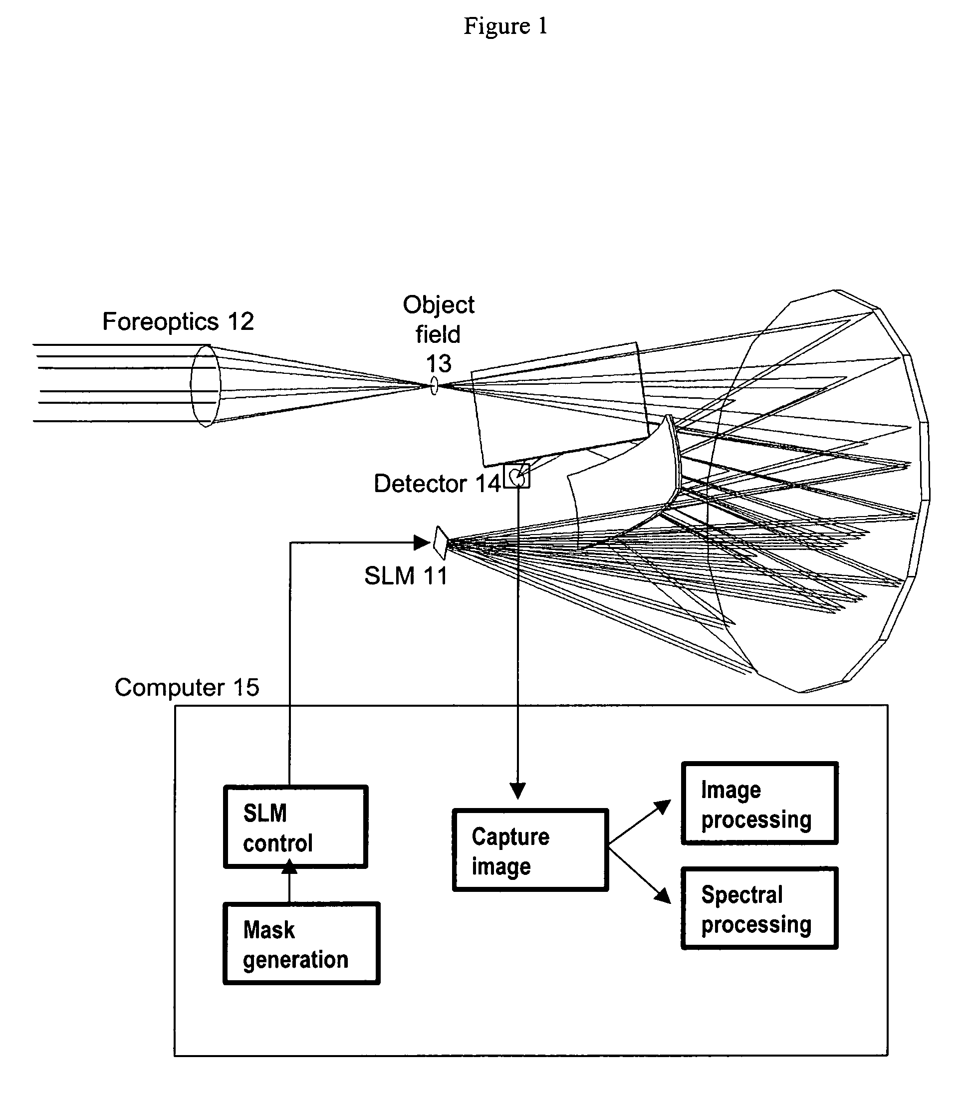
[0013]The current invention stems in part from the realization that overall image quality in a spectral encoder is improved by placing the dispersed image close to the center of curvature along the dispersion axis. One implementation of the invention uses the so-called vertical Offner orientation, in which light is dispersed in a direction perpendicular to the displacement direction. This keeps the dispersed image close to the center of curvature in the dispersion dimension, thereby reducing image aberrations, which grow non-linearly with displacement from the center of curvature. With this configuration, a single spectrograph, using only one grating and one other optical element with a curved surface to both disperse and recombine the image, can produce a high quality two-dimensional image. By contrast, the lateral Offner configuration requires two distinct gratings and four additional curved optical surfaces to produce similar image quality.
[0015]This invention also stems from the realization that the signal to noise ratio of spectral imagers and spectrographs can be improved by maximizing the total light collected per unit area of detector. The double pass spectrograph design increases the total light collection by recombining all the wavelengths of the input light onto a single detector element. For many applications, including most applications in the infrared at wavelengths greater than 3 microns, the system noise is limited by the size of the detector element. The double pass spectrograph of this invention accomplishes an efficient optical design that minimizes the image spot size. This design can make use of small detectors, therefore increasing the signal to noise ratio. Furthermore, light collection is optimized by omitting the slit in the spectrograph, and instead using the detector element in conjunction with the spectral mask to define the spectral pass bands of the system.
[0017]The spatial light modulator may be programmable and may comprise a two-dimensional digital micromirror array. The dispersing element may be a curved grating, and in the first optical path the dispersed image may be placed near to center of curvature of the grating along the dispersion direction, to reduce image aberrations. The imaging spectrograph in the first optical path may place the dispersed image near the aplanatic focus along the dispersion direction, to reduce image aberrations.

Problems solved by technology

The imaging performance is poor however along the dispersion direction, making this approach difficult for two-dimensional imaging applications.

Method used


Image

  • Spectral encoder
  • Spectral encoder
  • Spectral encoder

Examples


Embodiment Construction

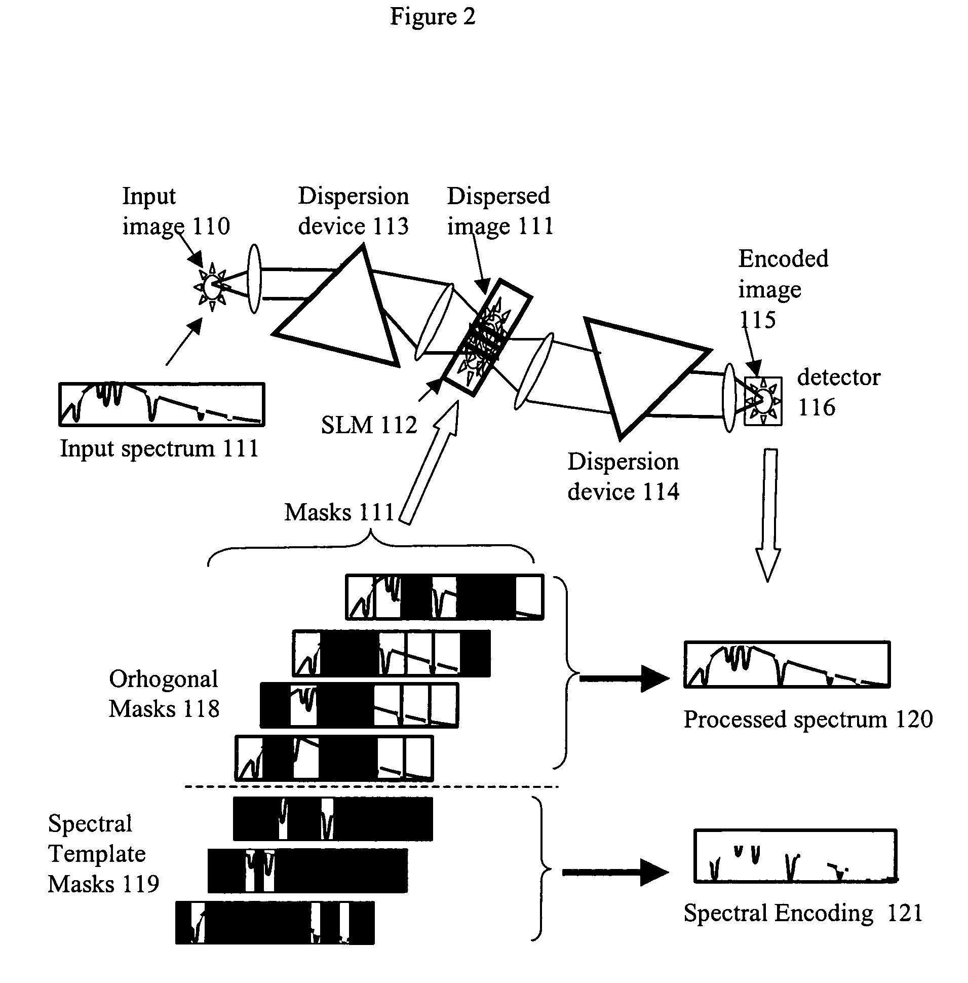
[0038]The preferred embodiment of the spectral encoder of this invention consists of a double-pass spectrograph with an intermediate encoding mask, and a detector. External means, such as foreoptics or optical fibers, are used to introduce a radiation field to the object plane of the spectrograph. The spectral encoder produces a spectrally encoded image of the object field on the detector. Using telescope foreoptics, the imager might investigate a distant scene, or using microscope foreoptics it might investigate a microscopic scene. Alternatively, using optical fibers it might measure radiation from multiple distant locations.

[0039]FIG. 1 shows one embodiment of a spectral encoder of the invention incorporating a programmable spatial light modulator (SLM) 11 that allows programmable and adaptive selection of the spectral pass bands. It incorporates a telescope foreoptic 12 to deliver an image into its input object field 13. It also uses one or more 2D detector arrays 14 to convert ...


PUM


Abstract

A spectral encoder for producing spectrally selected images of a radiation field containing multiple spectral components. An imaging spectrograph defines a first optical path that produces from the input radiation field a spectrally dispersed image comprising multiple spectral components displaced along a dispersion direction. Spectral pass bands are encoded on the dispersed image by a programmable spatial light modulator using one or more spatial masks. The imaging spectrograph further defines a second optical path that reverses the spectral dispersion of the first path and produces a spectrally-encoded polychromatic output image containing only those spectral components encoded by the spatial mask. The first and second optical paths share a common dispersing element. A detector records at least one spatial region of the spectrally encoded output image.

Description

STATEMENT REGARDING FEDERALLY SPONSORED RESEARCH[0001]This invention was made with government support under the following contracts: Fast Adaptive Spectrometer Programmable for the Evaluation of Combustion (FASPEC), Contract No. W31PQ-05-C-R095 (Army), Adaptive Spectral Imager (ASI) for the next generation EKV, Contract No. FA8718-04-C-0058 (MDA), Infrared Derivative Spectroscopy for Open Path Sensing, Contract No. W911SR-05-P-0063 (Army), and Chemical / Biological Agent Standoff Detection, Contract No. HDTRA1-05-P-0126 (DTRA). The government has certain rights in this invention.FIELD OF THE INVENTION[0002]This invention relates to a spectral encoder for recording polychromatic images with a programmable combination of spectral pass-bands. It can be used both to record spectrally filtered images and as a spectrometer to measure the spectrum of one or more spatial elements of a scene.BACKGROUND OF THE INVENTION[0003]Spectrally resolved images are widely used to identify features based ...

Claims


Application Information

Patent Timeline
Patent Type & Authority Patents(United States)
IPC IPC(8): G01J3/28
CPCG01J3/02G01J3/0208G01J3/021G01J3/0229G01J3/14G01J3/18G01J3/2823G01J3/2846
Inventor GOLDSTEIN, NEILVUJKOVIC-CVIJIN, PAJOFOX, MARSHA J.ADLER-GOLDEN, STEVEN M.LEE, JAMINECLINE, JASON A.GREGOR, BRIAN
Owner GOLDSTEIN NEIL
Learn More