Optical communication network using a code division multiplexing method

a technology of optical communication network and code division, applied in the field can solve the problems of increasing assembly cost and maintenance cost of optical communication network, destroying information stored in atm cells, and requiring more complex control of uplink direction time division multiplexing, so as to avoid optical signals and assembly at low cost, the effect of increasing throughpu

Active Publication Date: 2008-01-29
MARVELL ASIA PTE LTD
View PDF3 Cites 9 Cited by
  • Summary
  • Abstract
  • Description
  • Claims
  • Application Information

AI Technical Summary

Benefits of technology

[0012]The present invention performs Code Division Multiplexing of the transmission data and hence there is no risk of the optical signals that are transmitted by different transceivers colliding. Therefore, the communication network according to the present invention does not need to control data transmission timings of the transceivers, and hence can be assembled at low cost. In addition, the plurality of transceivers is able to transmit data at the same time, and therefore the throughput increases.

Problems solved by technology

On the other hand, uplink direction Time Division Multiplexing necessitates more complex control.
The information stored in these ATM cells is destroyed by this collision.
This equipment is responsible for an increase in the assembly costs and maintenance costs of the optical communication network.

Method used


Image

  • Optical communication network using a code division multiplexing method
  • Optical communication network using a code division multiplexing method
  • Optical communication network using a code division multiplexing method

Examples


first embodiment

[0025]The first embodiment of the present invention will now be described by taking an example in which the present invention is applied to a gigabit Ethernet communication network.

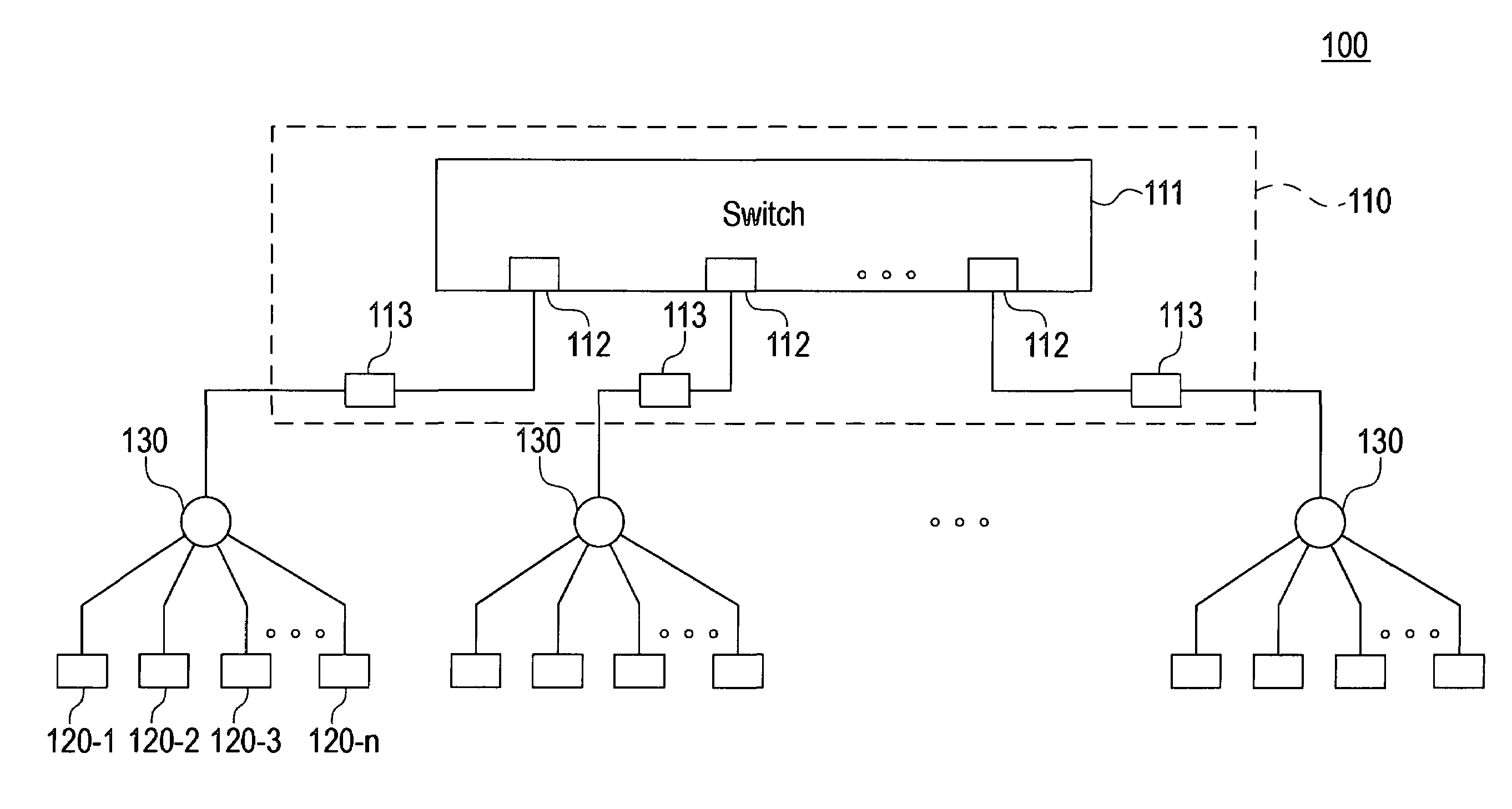
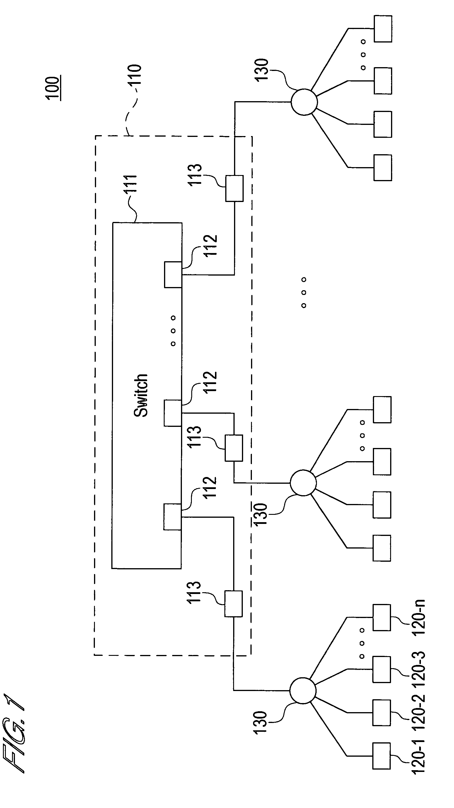
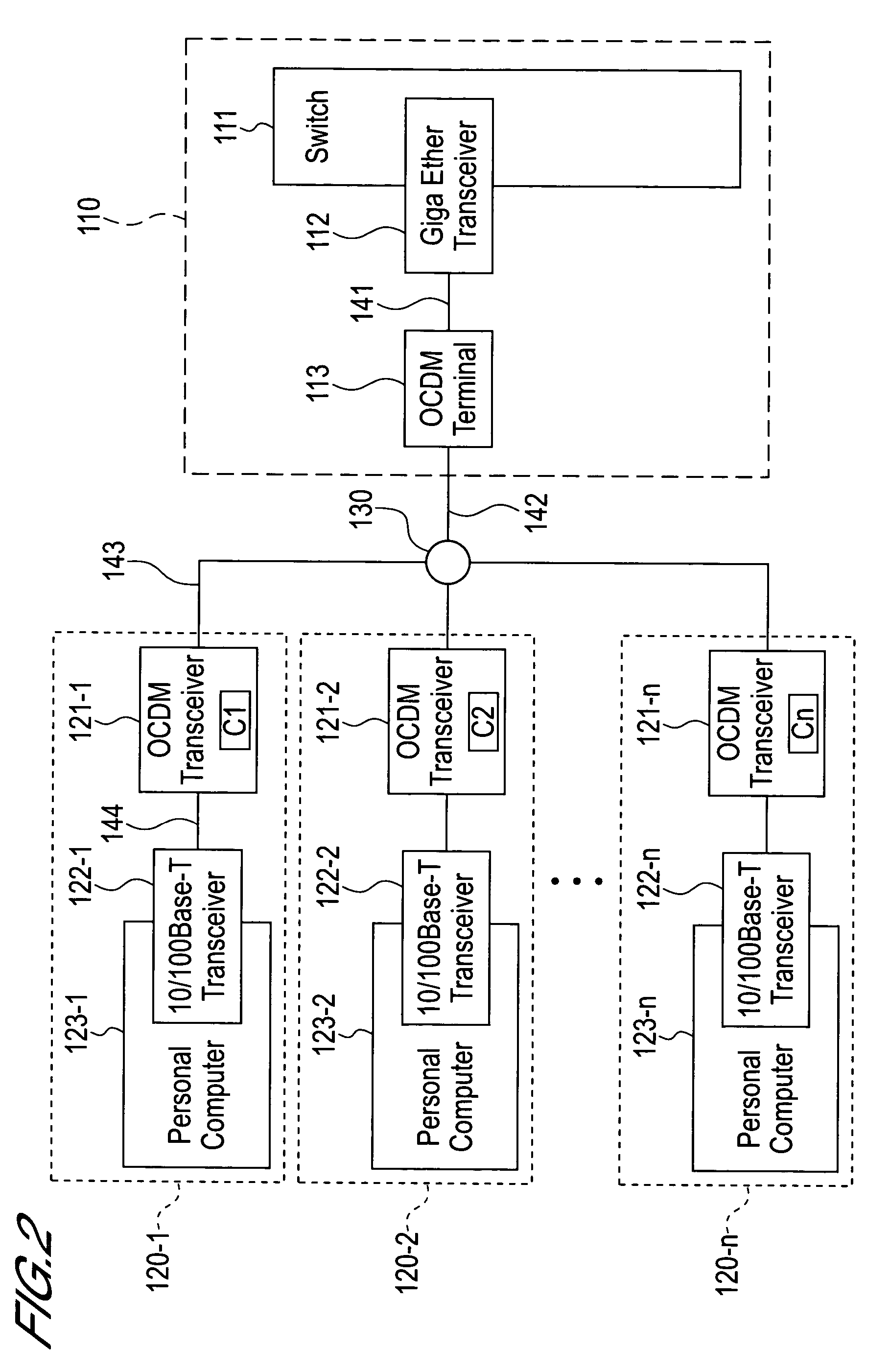
[0026]FIG. 1 is a block diagram that schematically shows the overall constitution of the optical communication network relating to this embodiment. Further, FIG. 2 shows the internal constitution of the accommodation device and communication terminals of FIG. 1. Only the constitution corresponding to a single port of the accommodation device is shown in FIG. 2.

[0027]As shown in FIG. 1, the optical communication network 100 relating to this embodiment comprises an accommodation device 110; a plurality of optical couplers 130, 130, . . . ; a plurality of communication terminals 120-1 to 120-n; electrical transmission paths 141, 144; and optical transmission paths 142, 143. As will be described subsequently, according to this embodiment, OCDM (Optical Code Division Multiplexing) technology is employed for up...

second embodiment

[0073]Next, the second embodiment of the present invention will be described by using FIGS. 7 and 8.

[0074]With the optical communication network relating to this embodiment, the constitution of the OCDM terminal and OCDM transceivers differs from that of the network of the first embodiment.

[0075]FIG. 7 is a block diagram showing the constitution of the OCDM terminal relating to this embodiment. In FIG. 7, the constituent elements assigned the same reference symbols as FIG. 3 are the same as those in FIG. 3.

[0076]As shown in FIG. 7, the OCDM terminal of this embodiment comprises a NACK packet assignment circuit 701.

[0077]When the decision circuit 303 decides that a data anomaly has occurred, the NACK packet assignment circuit 701 inputs data NT1 to NTn indicating this decision result. Then, a MAC frame in which information indicating this decision result is stored is generated and transmitted to the E / O converter 306. This MAC frame is converted into an optical signal by the E / O conv...

third embodiment

[0087]Next, the third embodiment of the present invention will be described by using FIGS. 9 and 10.

[0088]In the case of the optical communication network relating to this embodiment, the constitution of the OCDM terminal and OCDM transceivers differs from that of the network of the first embodiment.

[0089]FIG. 9 is a block diagram showing the constitution of the OCDM terminal relating to this embodiment. In FIG. 9, the constituent elements assigned the same reference symbols as in FIG. 3 are the same as those of FIG. 3.

[0090]As shown in FIG. 9, the OCDM terminal of this embodiment comprises optical de-spreaders 901-1 to 901-n and O / E converters 902-1 to 902-n.

[0091]The optical de-spreaders 901-1 to 901-n receive an input of an optical signal from the optical transmission path 142. The same optical signal is input to each of the optical de-spreaders 901-1 to 901-n. The optical de-spreader 901-1 performs de-spreading that corresponds with the spreading code C1. As a result, the OCDM t...


PUM


Abstract

The present invention is a high-speed and low-cost optical communication network. A preferred embodiment of this optical communication network comprises an accommodation device, optical couplers that are connected to corresponding ports of this accommodation device, and communication terminals that are connected to corresponding optical couplers. Further, data transmitted by the communication terminals to the accommodation device is code-division multiplexed. Because data collision is prevented by means of code division multiplexing, control of the timing with which the communication terminals transmit data is not required. Meanwhile, data transmitted by the accommodation device to the communication terminals is time-division multiplexed because there is no risk of collision.

Description

BACKGROUND OF THE INVENTION[0001]1. Field of the Invention[0002]The present invention relates to an optical communication network. More precisely, the present invention relates to a technology for adapting Optical Code Division Multiplexing to an optical communication network.[0003]2. Description of Related Art[0004]A network called an FTTx, for example, is known as an optical communication network. An FTTx is a communication network for connecting an accommodation device and subscriber buildings (homes, offices, and so forth) by means of optical fiber. As FTTx, FTTH (Fiber to the Home), FTTN (Fiber to the Neighborhood), FTTB (Fiber to the Building), and so forth, are known, for example. FTTx is used, for example, as an access system for connecting a subscriber computer terminal to the Internet.[0005]As a technology for implementing an FTTx, ATM-PON (Asynchronous Transfer Mode based Passive Optical Network), for example, is known. ATM-PON is able to implement broadband communication...

Claims


Application Information

Patent Timeline
Patent Type & Authority Patents(United States)
IPC IPC(8): H04J14/00H04B10/27H04B10/272H04J13/00H04J13/16H04J14/04H04J14/06H04J14/08
CPCH04J14/005
Inventor KASHIMA, MASAYUKIMATSUNO, KAZUHIKO
Owner MARVELL ASIA PTE LTD
Why Eureka
Try Eureka