Pressure apparatus and chip mounter

a technology of pressure apparatus and chip mounter, which is applied in the direction of metal working apparatus, gripping head, manufacturing tools, etc., can solve the problems of chip mouter head often suffering, and achieve the effect of shortened working period or tact tim

Inactive Publication Date: 2008-02-05
FUJITSU LTD
View PDF7 Cites 15 Cited by
  • Summary
  • Abstract
  • Description
  • Claims
  • Application Information

AI Technical Summary

Benefits of technology

[0006]It is accordingly an object of the present invention to provide a pressure apparatus and a chip mounter contributing to realization of a shortened working period or tact time.
[0008]The pressure apparatus allows the movable member to cause the axial movement of the support shaft. In this case, the first guide serves to guide the axial movement of the support shaft. The first guide is supported on the support member. The support member stands still or static during the movement of the movable member. Accordingly, the movement of the movable member is restrained in the axial direction. The contact member is thus prevented from suffering from a swinging movement around the force sensor. Servo control of a higher frequency bandwidth can be applied to the movement of the contact member. The contact member is allowed to move at a higher velocity. Occurrence of resonance is still avoided in the contact member. The contact member can be positioned at a predetermined position in a shorter period. The pressure apparatus is allowed to enjoy a shortened working period or tact time.
[0009]The first guide may be a non-contact guide effecting a predetermined force to the support shaft from at least pairs of opposite directions. A physical contact is thus reliably avoided between the support shaft and the first guide. The friction is avoided between the support shaft and the first guide. The support shaft thus starts moving in response to a driving force of a smaller magnitude. The load applied to the contact member can accurately be detected in the force sensor at a higher resolution. The pressure force of the contact member can be controlled with a higher accuracy. The force may employ a static pressure based on air, for example. On the other hand, if a contact guide is employed as the first guide, for example, a friction is induced between the support shaft and the first guide, so that the support shaft cannot start moving in response to a driving force of a smaller magnitude. The resolution of the force sensor in this manner depends upon the magnitude of the friction established in the first guide.
[0010]The second guide may likewise be a non-contact guide effecting a predetermined force to the movable member from at least pairs of opposite directions. A physical contact is reliably avoided between the movable member and the second guide. The friction is avoided between the movable member and the second guide. The support shaft thus starts moving in response to a driving force of a smaller magnitude. The load applied to the contact member can further accurately be detected in the force sensor at a higher resolution. The pressure force of the contact member can be controlled with a further higher accuracy. The force may employ a static pressure based on air, for example.
[0011]The force sensor may comprise: a connecting piece designed to connect the support shaft to the movable member; and a strain gauge attached to the connecting piece. The deformation of the connecting piece induces a strain in the strain gauge. A load is measured based on the strain. The strain gauge realizes an accurate measurement of a load based on a deformation of a larger amount. The larger the deformation gets in the strain gauge, the higher the accuracy of the measurement gets. The first guide serves to prevent generation of resonance in the contact member even if the connecting piece is apt to largely deform in response to application of a smaller load so as to obtain a larger deformation of the strain gauge.
[0012]The voice coil motor may be employed as the drive source. The voice coil motor enables a faster movement of the movable member, the support shaft and the contact member as compared with a driving mechanism utilizing a ball screw, air pressure, or the like. The tact time can be shortened.

Problems solved by technology

The head of the chip mouter often suffers from swinging movement around the load cell based on the imbalance of the mass.

Method used


Image

  • Pressure apparatus and chip mounter
  • Pressure apparatus and chip mounter
  • Pressure apparatus and chip mounter

Examples


Embodiment Construction

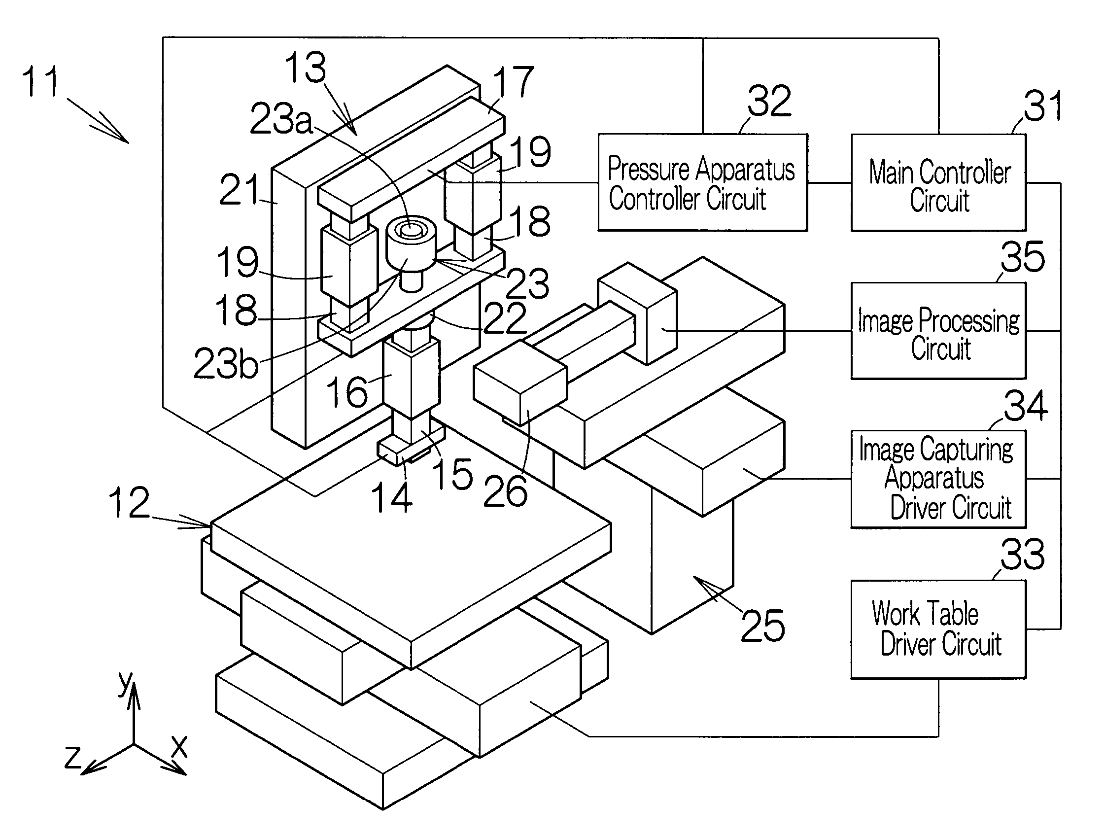
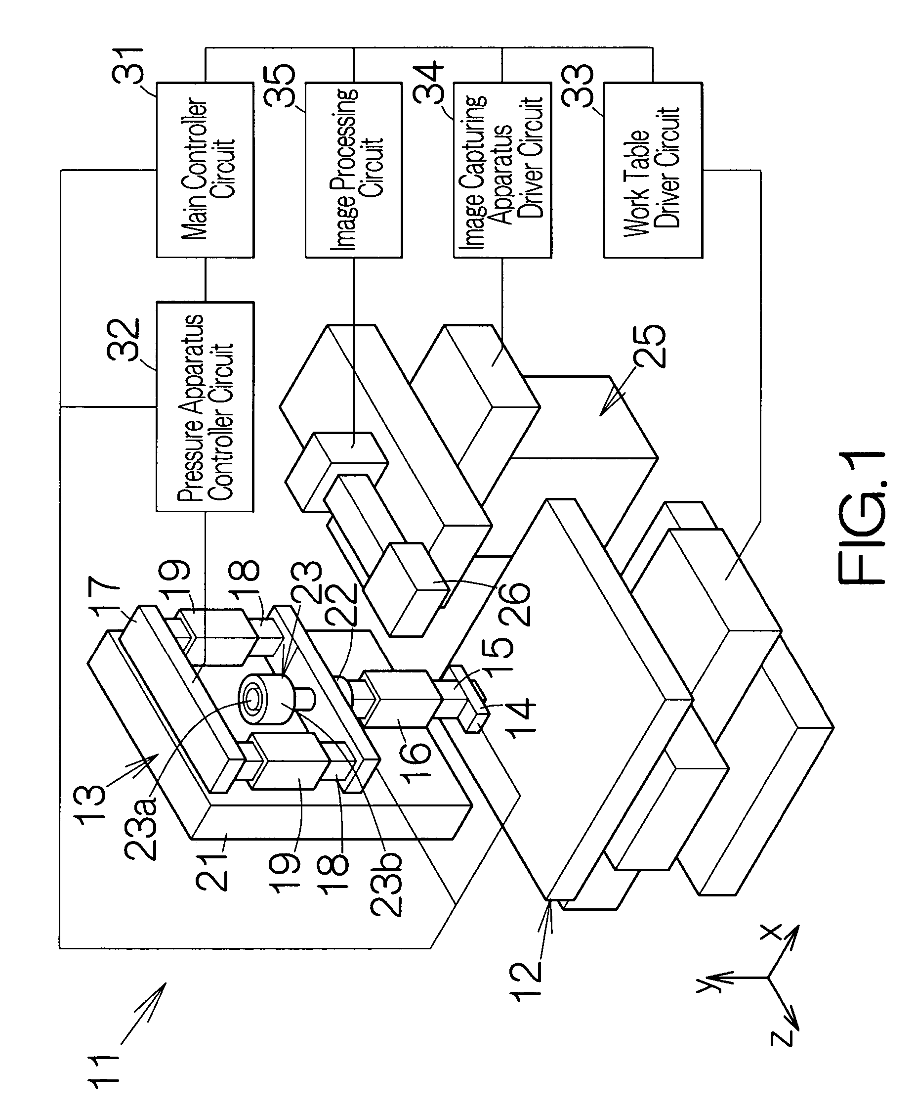
[0019]FIG. 1 schematically illustrates a chip mounter 11 according to an embodiment of the present invention. The chip mounter 11 includes a work table 12 defining the upper flat surface along a predetermined horizontal plane. The work table 12 is allowed to move within the horizontal plane. The work stage 12 is designed to receive a printed circuit board on the upper flat surface.

[0020]Here, the xyz-coordinate system is established in the chip mounter 11. The y-axis of the xyz-coordinate system extends in the direction perpendicular to the upper flat surface of the work table 12, namely to the horizontal plane. The work table 12 is driven in the x-axis and in the y-axis. The position of the work table 12 can be identified with the x-coordinate and the y-coordinate.

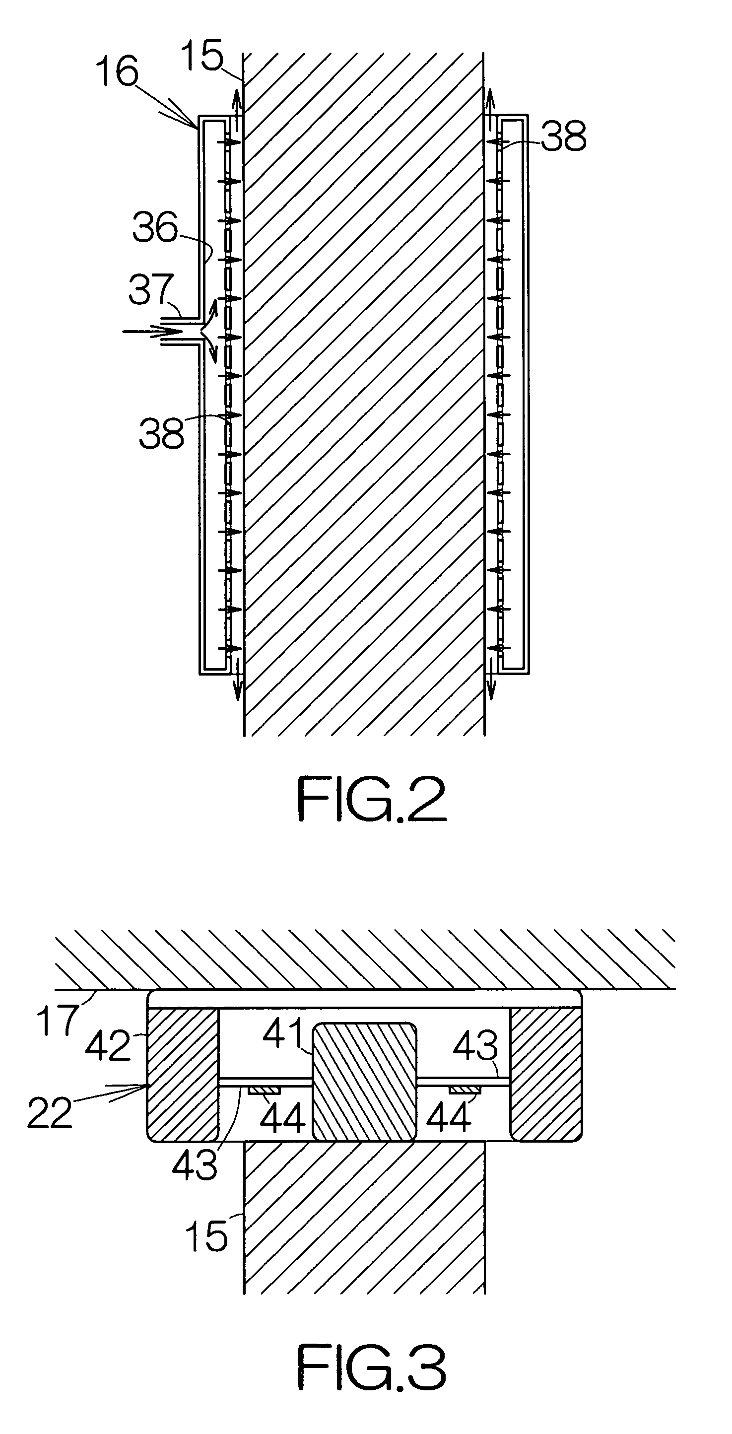
[0021]A pressure apparatus 13 is related to the work table 12. The pressure apparatus 13 includes an ultrasonic head 14 serving as a contact member according to the present invention. The ultrasonic head 14 serves to hold...


PUM

PropertyMeasurementUnit
pressureaaaaaaaaaa
forceaaaaaaaaaa
driving forceaaaaaaaaaa

Abstract

A contact member is supported on the support shaft. A force sensor is coupled to the support shaft. A movable member is coupled to the force sensor. The pressure apparatus allows the movable member to cause the axial movement of the support shaft. A first guide serves to guide the axial movement of the support shaft. The first guide is supported on the support member. The support member stands still during the movement of the movable member. Accordingly, the movement of the movable member is restrained in the axial direction. The contact member is thus prevented from suffering from a swinging movement around the force sensor. Servo control of a higher frequency bandwidth can be applied to the movement of the contact member. The contact member moves at a higher velocity. Occurrence of resonance is still avoided in the contact member. The tact time can be shortened.

Description

BACKGROUND OF THE INVENTION[0001]1. Field of the Invention[0002]The present invention relates to a pressure apparatus. In particular, the invention relates to a pressure apparatus incorporated in a chip mounter designed to mount an electronic component chip on a printed circuit board.[0003]2. Description of the Prior Art[0004]As disclosed in Japanese Patent Application Publication No. 2003-229442, for example, a chip mounter is well known. A contact member such as a head is opposed to the upper surface of a work stage in the chip mounter. The chip mounter includes a movable member designed to move in the direction perpendicular to the upper surface of the work stage. A guide is disposed to support the movement of the movable member. A support shaft is attached to the lower end of the movable member. A head is fixed to the lower end of the support shaft. A load cell is interposed between the support shaft and the movable member. When the head is urged against a substrate on the work ...

Claims


Application Information

Patent Timeline
Patent Type & Authority Patents(United States)
IPC IPC(8): B23P19/00A47J45/00
CPCH05K13/0404Y10T29/53187Y10T29/53178Y10T29/53183Y10T29/53191Y10T29/53174H05K13/046H05K13/0413H05K13/082
Inventor KOBAYASHI, TAIZANTAKADA, EIJIKUBOYAMA, MAKOTO
Owner FUJITSU LTD
Why Eureka
Try Eureka