Structural component of a motor vehicle bumper arrangement

a technology for bumpers and structures, applied in vehicle bodies, monocoque constructions, roofs, etc., can solve the problems of undesirably high local concentration of force, undue danger of fracture, and the risk of fracture to the lower leg of pedestrians is minimized, and the effect of reducing the risk of fracture to the lower leg

Inactive Publication Date: 2008-02-05
DECOMA GERMANY
View PDF26 Cites 29 Cited by
  • Summary
  • Abstract
  • Description
  • Claims
  • Application Information

AI Technical Summary

Benefits of technology

[0011]Accordingly, the object of the invention is to provide a structural component for mounting in a lower region of a motor vehicle bumper arrangement, by means of which the risk of fracture to the lower leg on hitting a pedestrian is minimized as much as possible and with which the disadvantages attached to the prior art as described above are overcome.
[0012]With the structural component according to the invention, in the event of frontal impact with a pedestrian, the bending angle of the pedestrian's lower leg on impact is restricted to the bumper as the lower leg is kept substantially parallel on making contact with the front covering. Thus, according to the invention, the rotation of the lower leg is limited, thus enabling uniform characteristics over the entire height of the impact zone in accordance with the pedestrian safety guidelines in force, i.e. the current EU regulations EURO NCAP. As the structural component according to the invention, which is intended for mounting in a lower region of a bumper arrangement, has a spring characteristic in relation to bending stress which is substantially perpendicular to its longitudinal extent, and which is matched to the spring characteristic of an adjacent part of the bumper arrangement located above it, a harder response is achieved, compared with conventional arrangements, for the bumper arrangement in the event of bending deformation in the direction of travel, i.e at right angles to the longitudinal extent of the bumper arrangement. At this, the bumper arrangement is deformed uniformly, viewed over its height. This so-called harder response of the structural component according to the invention, or of a bumper arrangement provided therewith, reduces the bending angle, as already explained, in relation to the lower leg of the affected pedestrian.

Problems solved by technology

Bumper arrangements or bumper assemblies on modern motor vehicles are generally complex assemblies as the bumper arrangements have to meet a variety of requirements simultaneously, e.g., in terms of a favorable coefficient of air resistance, optical individualization of the vehicle or effective impact protection for pedestrians in order to meet current accident prevention requirements.
However, a disadvantage of this bumper arrangement is that rigidity in a direction at right angles to the transverse carrier or transverse bar is higher in an area adjacent to the transverse bar, i.e. in a lower region of the bumper arrangement, and thus involves a greater risk of fracture to the lower leg of a pedestrian.
A disadvantage of this is that an undesirably high local concentration of force may be produced in the pedestrian's leg area, once again involving an undue danger of fracture.
A number of conventional bumper systems have the disadvantage that they do not meet, or only partly meet, the complete list of points of the current European regulations on pedestrian safety, i.e. the so-called EURO NCAP.

Method used


Image

  • Structural component of a motor vehicle bumper arrangement
  • Structural component of a motor vehicle bumper arrangement
  • Structural component of a motor vehicle bumper arrangement

Examples


Embodiment Construction

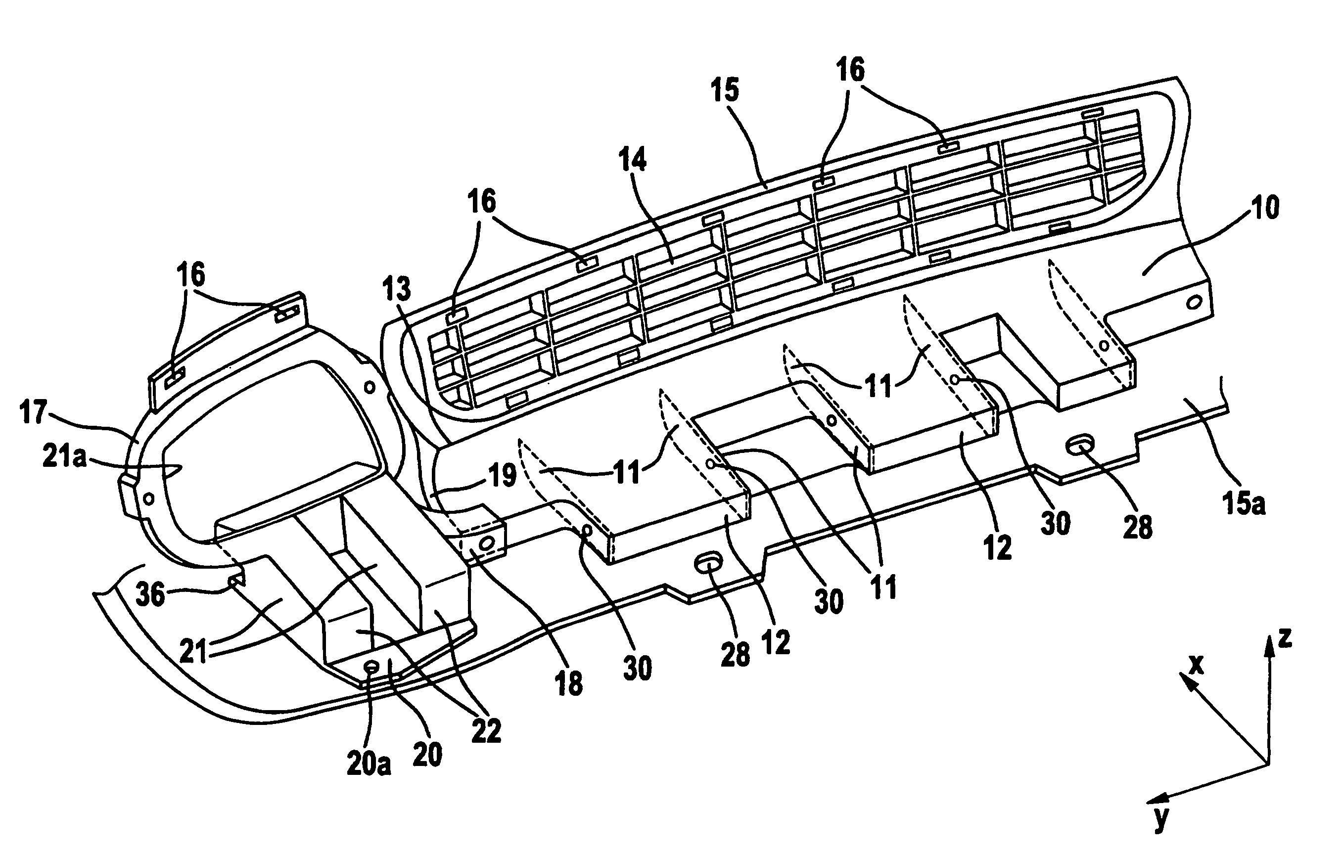
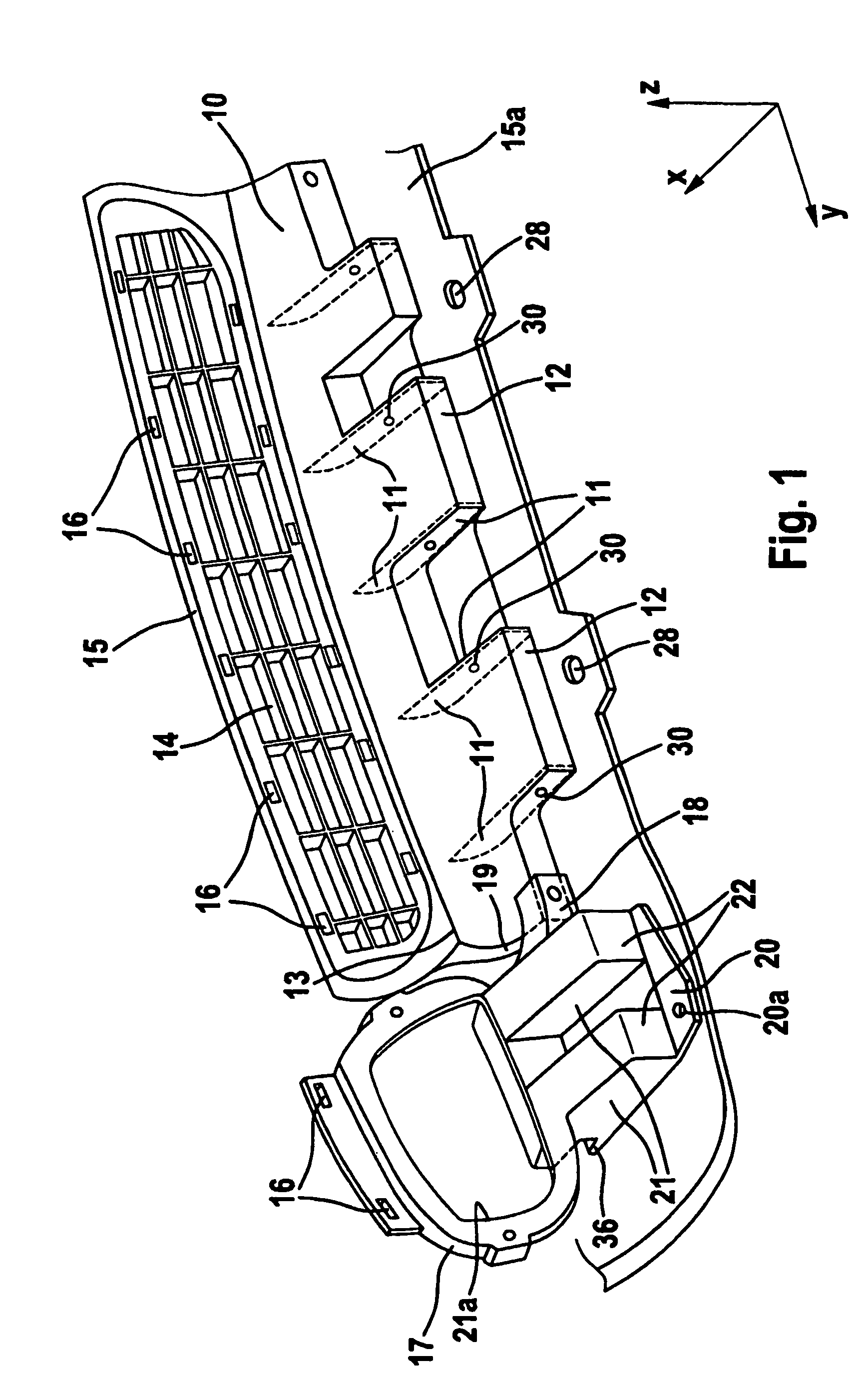
[0034]FIG. 1 shows an embodiment of a structural component 10 according to the invention viewed in perspective from behind, i.e. viewed as from an engine compartment. Because of the symmetrical nature of the structural component, only a left hand region thereof is shown in FIG. 1. The structural component 10 has a longitudinal dimension in the direction y. Over the width of the structural component, i.e. along the longitudinal dimension in the direction y, a plurality of reinforcing elements 11 are provided in the form of reinforcing ribs which extend substantially at right angles to the longitudinal dimension of the structural component 10, i.e. in the direction x.

[0035]The respective reinforcing ribs 11 are shown by broken lines in FIG. 1. The alignment of the respective reinforcing ribs 11 in direction x, corresponding to the direction of travel of a motor vehicle, and a suitably selected thickness for the reinforcing ribs 11 and their length in the direction x influence a spring...


PUM


Abstract

A structural component for mounting in a lower region of a motor vehicle bumper arrangement comprises a longitudinal dimension and is constructed in cross-section such that its spring characteristic in relation to bending stress in a direction (x) substantially at right angles to its longitudinal dimension corresponds substantially to the spring characteristic of a part of the bumper arrangement located above and adjacent to the structural component.

Description

CROSS-REFERENCE TO RELATED APPLICATIONS[0001]This application is a U.S. national stage application of PCT Application No. PCT / IB2004 / 004054, filed Dec. 4, 2004, which claims priority to German Application No. 10358473.0, filed Dec. 9, 2003.BACKGROUND OF THE INVENTION[0002]1. Field of the Invention[0003]The invention relates to a structural component for mounting in a lower region of a motor vehicle bumper arrangement or bumper assembly.[0004]2. Description of the Related Art[0005]Bumper arrangements or bumper assemblies on modern motor vehicles are generally complex assemblies as the bumper arrangements have to meet a variety of requirements simultaneously, e.g., in terms of a favorable coefficient of air resistance, optical individualization of the vehicle or effective impact protection for pedestrians in order to meet current accident prevention requirements.[0006]Document DE 199 21 480 A1 describes a front spoiler for a motor vehicle. The front spoiler can be extended in the long...

Claims


Application Information

Patent Timeline
Patent Type & Authority Patents(United States)
IPC IPC(8): B60K7/00B60R19/12B60R19/48B60R21/34
CPCB60R19/12B60R19/48B60R21/34
Inventor ZACHEISS, SVENRAIM, PETERDIEHL, PETER
Owner DECOMA GERMANY
Why Eureka
Try Eureka