Brake air drying using low pressure desiccant wheel

a desiccant wheel and brake air technology, applied in the direction of air treatment device, dispersed particle separation, separation process, etc., can solve the problems of affecting the system, affecting the operation of the valve,

Inactive Publication Date: 2008-02-05
UOP LLC
View PDF14 Cites 27 Cited by
  • Summary
  • Abstract
  • Description
  • Claims
  • Application Information

AI Technical Summary

Problems solved by technology

As the air cools in the system, it loses its capability to retain as much moisture, which results in the formation of liquid water in the system.
This moisture and other contaminants can be detrimental to the system in that freezing or sludge buildup can occur.
Excessive moisture can also wash away needed lubricants in the valves and other air system components.
If there is too long a period before regeneration occurs, then the desiccant will become saturated and the air dryer effectively stops functioning.
In the

Method used


Image

  • Brake air drying using low pressure desiccant wheel
  • Brake air drying using low pressure desiccant wheel
  • Brake air drying using low pressure desiccant wheel

Examples


Embodiment Construction

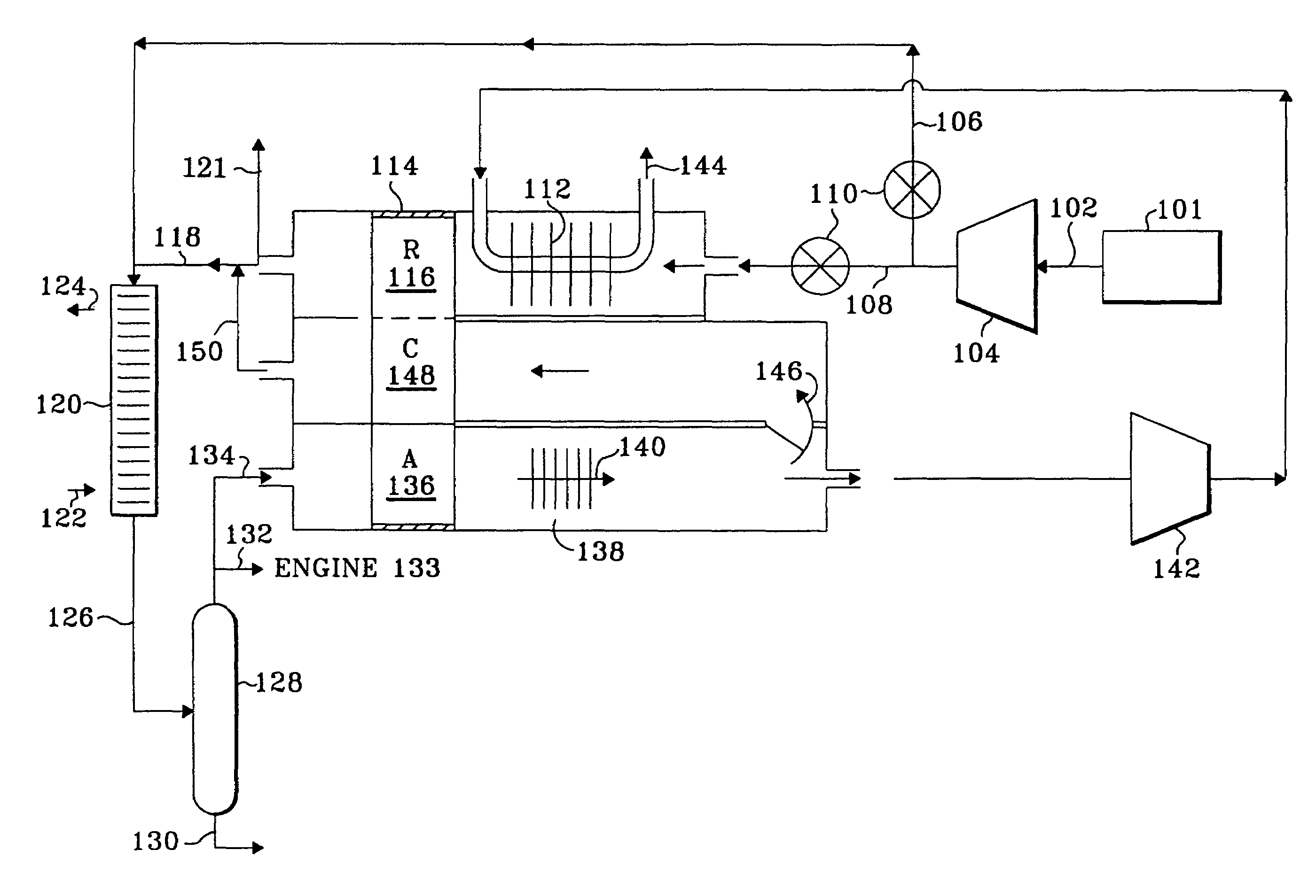
[0014]In the present invention, a desiccant wheel is located upstream of the air compressor to dry the brake air and eliminate the pressure swing dryer. Similar to the prior art, ambient air is drawn in through the engine air filter, which removes particulate contaminants. The air then enters the suction side of a turbocharger or super charger, which boosts the pressure to about 103 kPa (15 psig). An intercooler is used to cool the air. Most of the boosted air then enters the engine intake, but a portion of it (nominally 12 SCFM, but varying according to the engine speed) flows to the air compressor and then to the braking system.

[0015]Prior to entering the air compressor, the pressure boosted air flows through the adsorption sector of a desiccant wheel. Most of the dried air from the wheel then flows to the air compressor suction. However, a slipstream portion of the dried air is separated and used for regeneration of the wheel. This slipstream portion flows through a heat exchange...


PUM

PropertyMeasurementUnit
Temperatureaaaaaaaaaa
Pressureaaaaaaaaaa
Flow rateaaaaaaaaaa

Abstract

The invention comprises a temperature swing adsorption system for providing dry air to an air brake system. More particularly, there is provided a desiccant wheel upstream of the air compressor to dry air prior to its compression.

Description

FIELD OF THE INVENTION[0001]The present invention relates to the use of an adsorbent wheel in a temperature swing adsorption system to dry brake air. This invention is useful in the air brake systems of trucks and some other large vehicles.BACKGROUND OF THE INVENTION[0002]Compressed air systems are widely used to operate a number of devices, and find particular use in braking systems for heavy vehicles. These systems include an air compressor which compresses ambient air and charges a storage reservoir. The compressor is engine operated and a governor or controller, responsive to the reservoir pressure, selectively enables or disables the compressor as needed. Air dryers commonly employ a drying material or desiccant through which air passes to remove moisture and limit problems associated with moisture entering brake system components. Moisture is adsorbed by the desiccant and removed from the compressed air before it is transported to the storage reservoir. In these known systems,...

Claims


Application Information

Patent Timeline
IPC IPC(8): B01D53/06
CPCB01D53/06B60T17/004B01D53/0462B01D2253/108B01D2259/4566
Inventor COHEN, ALAN P.DUNNE, STEPHEN R.SETHNA, RUSTAM H.
Owner UOP LLC
Why Eureka
Try Eureka