Multiple leg tumbling robot

a robot and multi-leg technology, applied in the field of vehicle or robot locomotion, can solve the problems of high cost of road network, easy jamming of toy cars, and poor performance of wheels on terrain, and achieve the effect of saving weigh

Inactive Publication Date: 2008-02-05
HLYNKA ADRIAN GREGORY +1
View PDF19 Cites 52 Cited by
  • Summary
  • Abstract
  • Description
  • Claims
  • Application Information

AI Technical Summary

Benefits of technology

[0159]As mentioned earlier, given a strong enough power source, a robot using our invention can accelerate rapidly and even jump into the air. A compressed air or gas tank could provide bursts of power for jumping. Some of the energy could be recovered upon landing. The legs can actively cushion

Problems solved by technology

In practice wheeled vehicles need prepared roads because wheels do not perform well on terrain unless they are much larger than any irregularities of the terrain.
For example, toy cars easily get stuck except on smooth, clean floors.
Full-sized cars and trucks require a very expensive network of roads.
Off-road vehicles typically have huge wheels to roll over irregularities, and still must proceed with careful attention to obstacles.
Attempts have been made at mechanical walking, but there are few practical applications.
In the prior art, technological attempts to mimic animal locomotion have been clumsy.
Controlling these motions has proven difficult.
Controlling them in such a way to overcome obstacles presents further difficulties.
Legged locomotion presents problems of balance, especially when the legs are few.
With four, six, or more legs, balance is less of an issue because it is possible to have three feet on the ground at all times. However, controlling the many degrees of freedom becomes more of a problem.
Practically all vehicles (legged and wheeled) and animals get into difficulty if they become flipped on their side or upside down.
This

Method used


Image

  • Multiple leg tumbling robot
  • Multiple leg tumbling robot
  • Multiple leg tumbling robot

Examples


first preferred embodiment

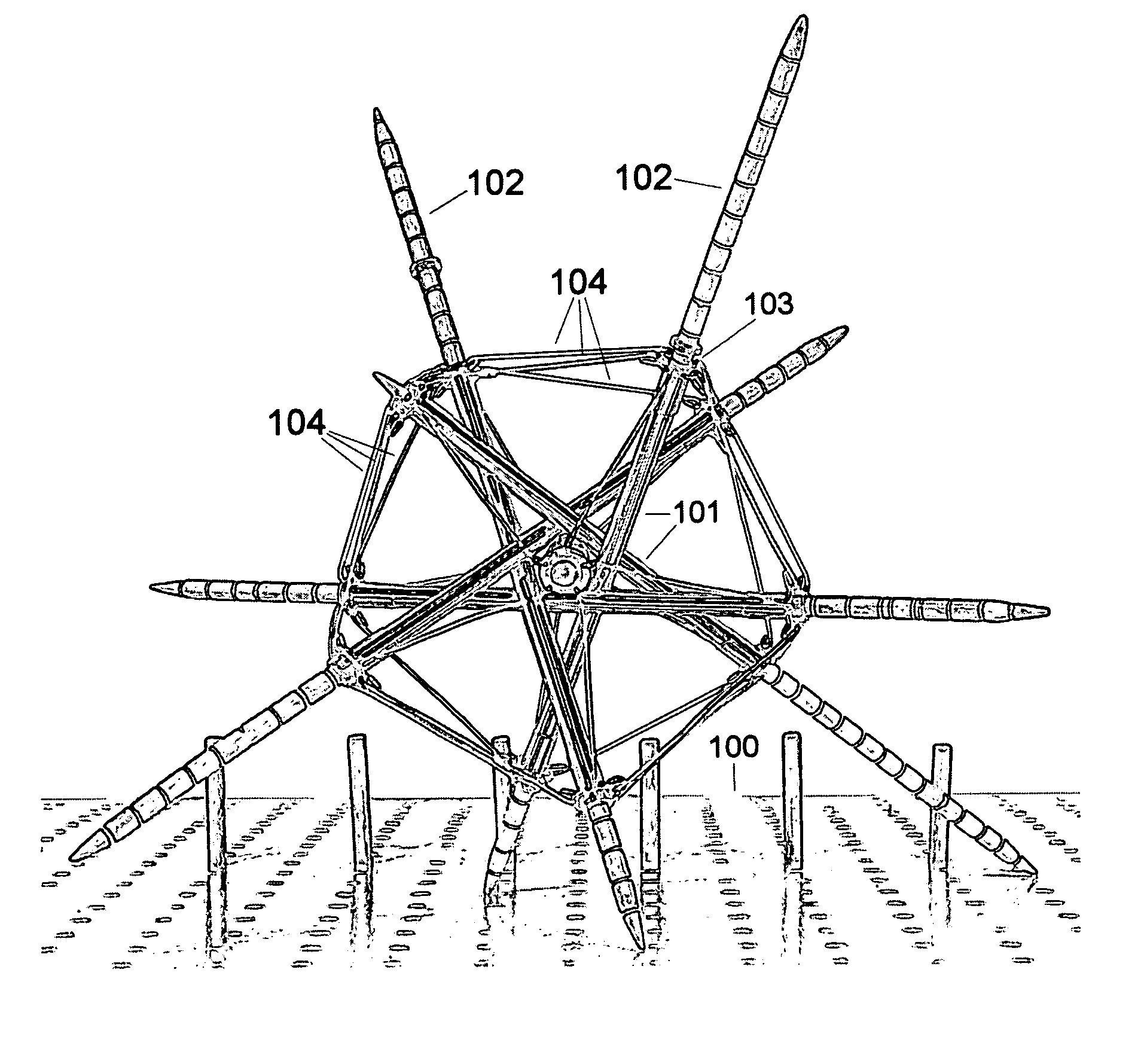
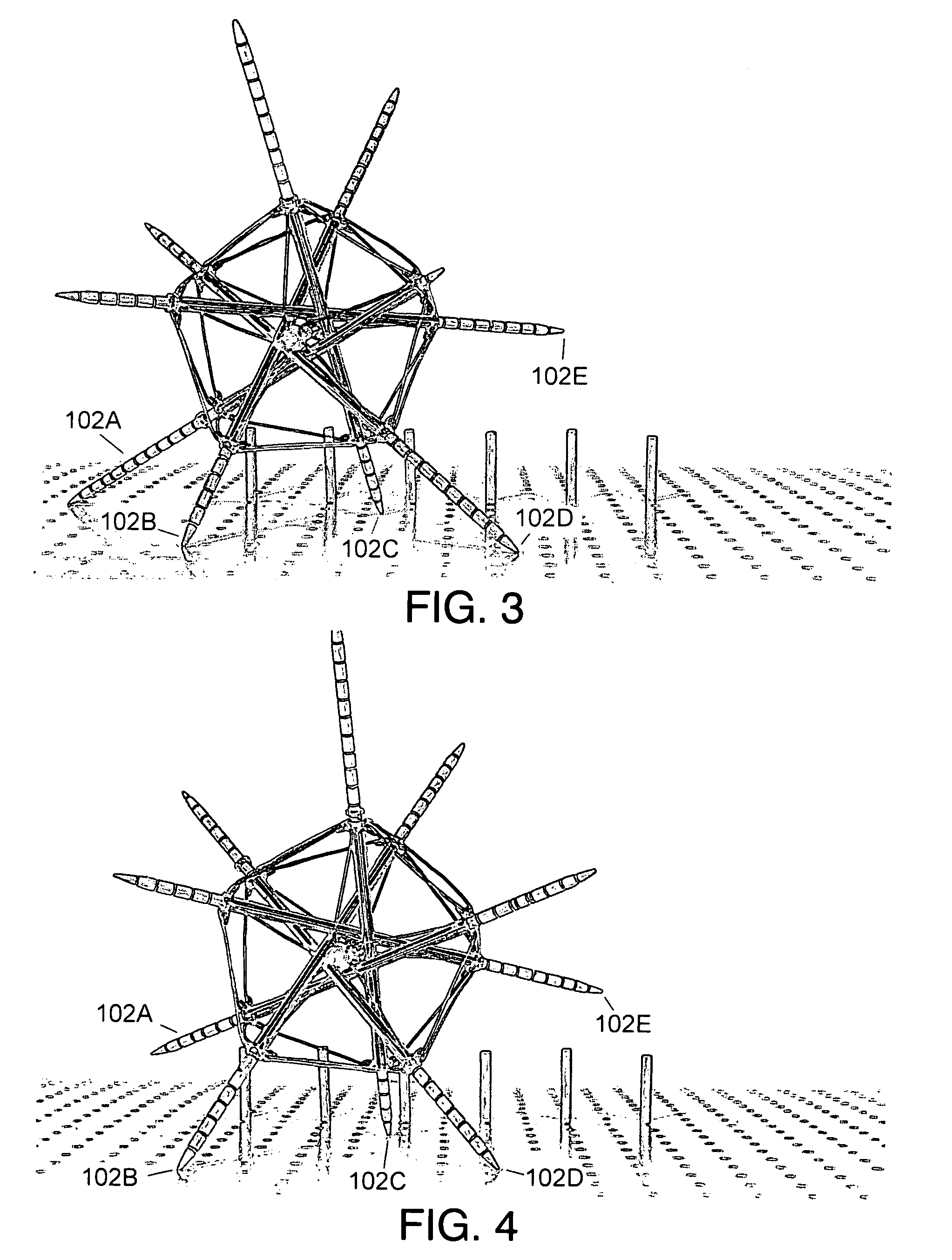
[0091]In this embodiment the robot is supported by three or four legs when stationary, regardless of its orientation. FIG. 3 shows the robot standing on legs 102A, 102B, 102C, and 102D, resting on a flat surface.

[0092]The motion of the legs is simply to extend and retract, radially from the approximate center of the robot. The robot in its entirety tumbles or rolls because of coordinated motion of the legs.

[0093]To start moving in an arbitrary direction, the one or two legs in the direction of the desired motion (of the three or four legs on the ground) are retracted, and the one or two trailing legs are extended. This starts the robot rolling.

[0094]FIG. 4 shows the robot of FIG. 3 slightly rotated. It shows leading legs 102C and 102D retracted, and trailing leg 102B extended, and leg 102A off the ground.

[0095]FIG. 5 shows continued tumbling motion; supported by legs 102B, 102C, and 102D.

[0096]FIG. 6 shows trailing leg 102B off the ground and leg 102E has touched the ground for the ...

second preferred embodiment

[0115]Compared to the first preferred embodiment, this vehicle is more complex and more capable. This vehicle moves based on the same principles as the first embodiment. This embodiment is meant to serve as a remotely controlled reconnaissance or surveillance robot.

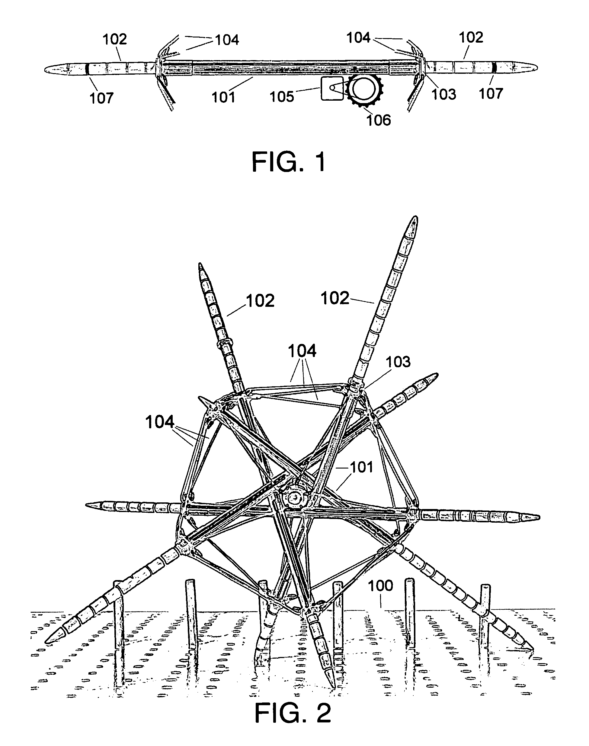
[0116]FIG. 10 shows a fully retractable leg assembly. It is like the leg assembly of FIG. 1 except that the leg member 102 is short enough to fit within the cylinder 101. This allows the legs of this vehicle to be fully retracted when not supporting the vehicle. This is important because the retracted legs will not get in the way of possible overhead obstacles, an important advantage in areas of overhead vegetation or when navigating through damaged buildings.

[0117]In operation, the intermediate sliding sleeve 108 is extended from the cylinder 101 by half the distance that the leg member 102 is extended. This telescoping action allows this dual-acting leg assembly to extend nearly as far as the simpler leg assembly of FIG...

third preferred embodiment

[0139]The robot of FIG. 16 locomotes by tumbling in the same way as the first preferred embodiment.

[0140]To fold the robot of FIG. 16, one pulls the five leg ends surrounding the north pole towards that pole, and the five surrounding the south pole towards that pole. The ten equatorial cords stretch, and the polar wires either become loose or retract, depending on the exact design, as can be seen in FIGS. 17 and 18.

[0141]If the robot needs to fold itself, without outside influence, it incorporates a means to retract its north and south polar tension cables simultaneously. The ten equatorial tension cords stretch or extend in response. The ends of all the legs draw together at the poles, as can be seen in FIGS. 17 and 18.

[0142]FIG. 17 shows the same robot of FIG. 16 partially folded. The polar tension wires are partly retracted, which causes the equatorial cords to stretch.

[0143]FIG. 18 shows the fully folded configuration of the robot. The polar wires are fully retracted and the fiv...


PUM


Abstract

A robot or vehicle locomotes by tumbling. Legs distributed over the surface of the robot individually extend or retract. A control system coordinates the action of the legs to cause the robot to tumble in any direction. A robot using this form of locomotion is highly maneuverable, can climb slopes, and can step over obstacles. It can provide a smooth ride on rugged terrain. A variation can jump into the air and land safely. A variation can be built with as few as six moving parts, can fold to fit into a projectile, and instantly unfold on landing. It may use airbags instead of legs. It can include a video system without moving parts that produces a stable, non-tumbling view of its surroundings while tumbling. It is an ideal remotely operated vehicle for search and rescue, firefighting, or reconnaissance for the military or police.

Description

CROSS-REFERENCE TO RELATED APPLICATIONS[0001]NoneFEDERALLY SPONSORED RESEARCH[0002]Not ApplicableSEQUENCE LISTING OR PROGRAM[0003]Not ApplicableBACKGROUND OF THE INVENTION[0004]1. Field of the Invention[0005]This invention generally relates to vehicle or robot locomotion, specifically to an improved and simplified system of using legs to propel a vehicle or robot.[0006]2. Prior ArtWheels, Legs, Obstacles, and Terrain[0007]Human technology has had great success with vehicles on wheels. In practice wheeled vehicles need prepared roads because wheels do not perform well on terrain unless they are much larger than any irregularities of the terrain. For example, toy cars easily get stuck except on smooth, clean floors. Full-sized cars and trucks require a very expensive network of roads. Trains require smooth steel rails. Off-road vehicles typically have huge wheels to roll over irregularities, and still must proceed with careful attention to obstacles.[0008]Tracked vehicles use continuo...

Claims


Application Information

Patent Timeline
IPC IPC(8): B25J5/00
CPCB25J19/0091B62D57/02B62D57/022
Inventor HLYNKA, ADRIAN GREGORYHLYNKA, CHRISTOPHER GREGORY
Owner HLYNKA ADRIAN GREGORY
Why Eureka
Try Eureka