Pulse-frequency mode DC-DC converter circuit

a converter circuit and pulse-frequency technology, applied in the direction of electric variable regulation, process and machine control, instruments, etc., can solve the problem of increasing the cost of building a regulator circuit using the regulator circuit, and achieve the effect of reducing gate charge dissipation and optimizing efficiency

Active Publication Date: 2008-02-05
VIA TECH INC
View PDF11 Cites 49 Cited by
  • Summary
  • Abstract
  • Description
  • Claims
  • Application Information

AI Technical Summary

Benefits of technology

[0008]In one set of embodiments, a switching power regulator for performing DC-to-DC (DC-DC) conversion may operate in pulse-frequency mode (PFM) based on peak current sense to regulate the load current with a variable frequency to achieve high efficiency at wide load variation without requiring an external diode component.
[0011]Should the load current increase when, as a result of operating in PFM, Vout falls below the ‘low’ threshold of the skip mode comparator, the power regulator may automatically transition into fixed-frequency PWM mode. During PFM operation, the PMOS transistor may be turned on at a frequency and duty cycle (for PWM) that is a function of the power regulator input voltage, the power regulator output voltage, and the value of the inductor, and the NMOS transistor may be kept off to optimize efficiency by reducing gate charge dissipation. The output voltage of the power regulator may therefore be regulated by skipping switching cycles that turn on the PMOS transistor.

Problems solved by technology

Although regulator circuit 200 operates in PFM, it requires external “catch” diode 124 for its operation, which increases the cost of building a regulator using regulator circuit 200.

Method used


Image

  • Pulse-frequency mode DC-DC converter circuit
  • Pulse-frequency mode DC-DC converter circuit
  • Pulse-frequency mode DC-DC converter circuit

Examples


Embodiment Construction

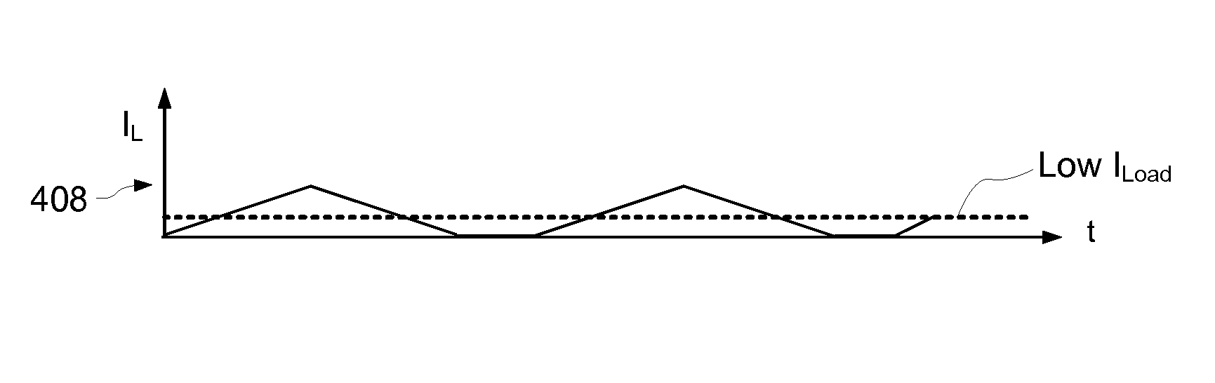
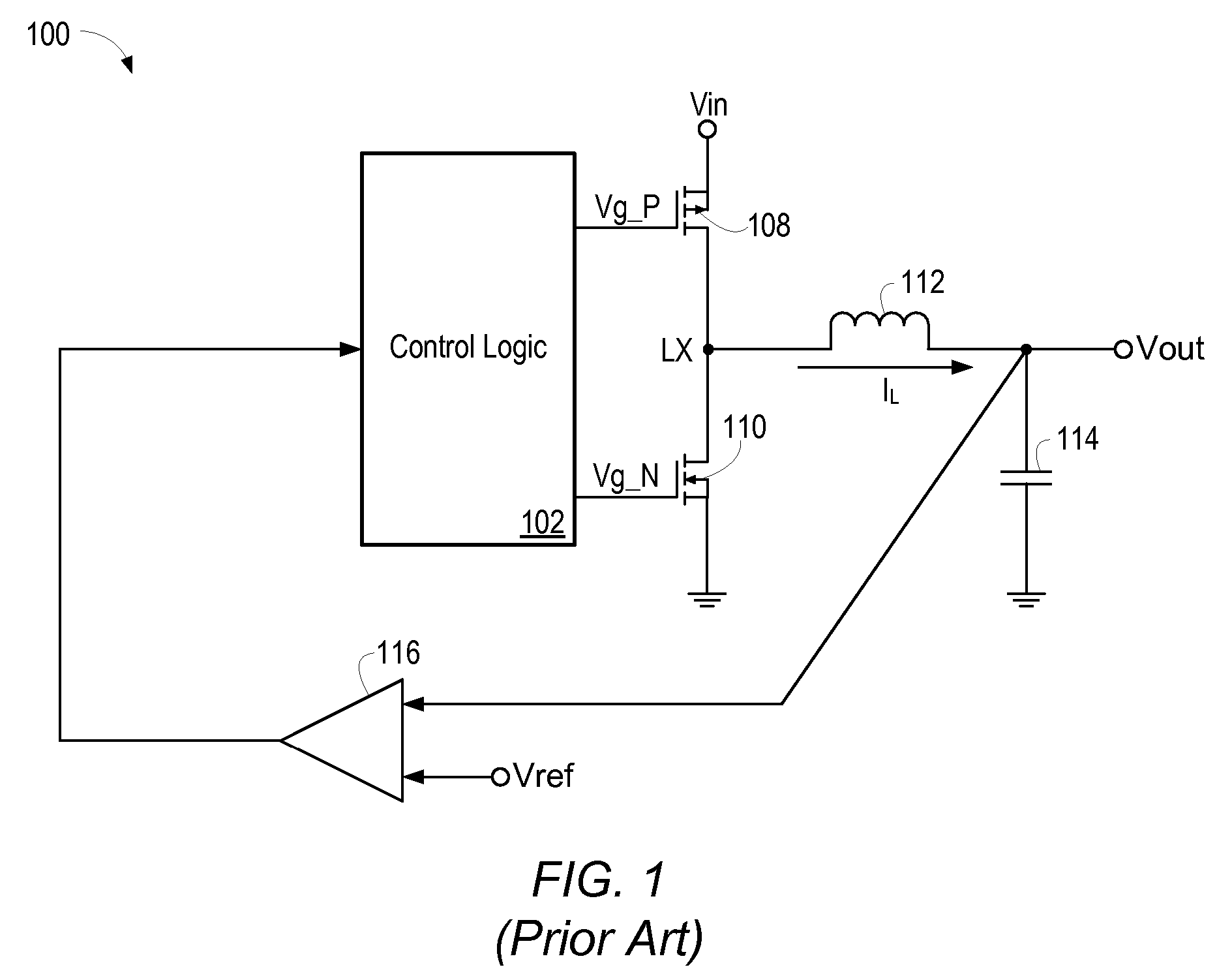
[0022]Referring again to FIG. 1, operation of a synchronous buck converter may be further examined. FIG. 3 shows voltage waveforms Vg_P 202, Vg_N 204, and Vx 206 (voltage at node LX), as well as inductor current IL 208 and corresponding load current ILoad as observed during high current load operation of synchronous buck converter 100. When Vg_P 202 is logic low, transistor 108 is turned on. When Vg_N is logic high, transistor 110 is turned on. The deadtime delay tdead indicates the time period when both transistors are turned off. As shown in FIG. 3, the average inductor current (i.e. the average of IL) is essentially equal to the DC load current provided by converter 100, indicated in FIG. 3 as ILoad. FIG. 4 shows a timing diagram of the inductor current (and correspondingly the DC load current) observed during light current load operation of converter 100. As seen in FIG. 4, when ILoad is less than half the magnitude of the peak-to-peak ripple of current IL, the entire IL wavefor...


PUM


Abstract

A step-down switching voltage regulator may operate in PFM mode based on peak current sense without requiring an external diode. The regulator may comprise a PMOS transistor and an NMOS transistor whose drains are coupled to a common output node and whose sources are coupled to high and low supply voltages, respectively, configured to develop a current in an inductor and generate an output voltage. A control circuit, coupled to the respective gates of the PMOS transistor and the NMOS transistor, may sense the current in the inductor (IL), sense an attenuated version of the output voltage (VFB), and sense the polarity of the voltage (VX) developed at the common output node. The control circuit may turn on the PMOS transistor when the VFB falls below a reference voltage and VX remains positive with respect to the low supply voltage, and may turn off the PMOS transistor when IL reaches a specified value or when VFB exceeds the reference voltage. The control circuit may also turn on the NMOS transistor after the PMOS transistor is turned off and VX becomes negative with respect to the low supply voltage, and may turn off the NMOS transistor when VX becomes positive with respect to the low supply voltage.

Description

[0001]This application claims benefit of priority of U.S. provisional application Ser. No. 60 / 595,236 titled “Pulse-Frequency Mode DC-DC Converter Circuit”, filed Jun. 17, 2005.BACKGROUND OF THE INVENTION[0002]1. Field of the Invention[0003]This invention relates to power converters in computer systems and digital systems, and more particularly to designing a DC-to-DC voltage converter.[0004]2. Description of the Related Art[0005]DC-to-DC conversion is often performed by having switching power regulators, or step-down regulators, converting a higher voltage (e.g. 12V) to a lower value as required by one or more load devices. A common architecture features distribution of the higher voltage to multiple power regulators, each producing a different (or possibly the same) voltage to one or more loads. Switching power regulators often use two or more power transistors to convert energy at one voltage to another voltage. One common example of such a power regulator, commonly called a “Buc...

Claims


Application Information

Patent Timeline
Patent Type & Authority Patents(United States)
IPC IPC(8): G05F1/565
CPCH02M3/1588H02M2001/0009Y02B70/1466H02M1/0009Y02B70/10
Inventor HO, DANIEL
Owner VIA TECH INC
Why Eureka
Try Eureka