Method and a circuit for deriving a synchronisation signal from a video signal

a synchronisation signal and video signal technology, applied in the direction of signal generators with optical-mechanical scanning, picture reproducers using projection devices, television systems, etc., can solve the problems of masking horizontal sync signals, video signals may suffer, and noise levels, so as to achieve accurate determination of the location of horizontal sync signals and make relatively rapid effects

Active Publication Date: 2008-02-05
ANALOG DEVICES INC
View PDF11 Cites 16 Cited by
  • Summary
  • Abstract
  • Description
  • Claims
  • Application Information

AI Technical Summary

Benefits of technology

[0074]A further advantage of the invention is that the value of the intermediate slice level signal can be determined without the need for locating positive going and negative going edges of the video signal, thereby avoiding any danger of a portion of the active video signal being misinterpreted as forming a horizontal sync signal.
[0075]Additionally, by virtue of the fact that by using the method according to the invention it is not necessary to determine the precise values of the blanking level and the sync tip level in order to determine the intermediate slice level signal, rapid lock-in of the video signal can be achieved, and since the blanking level and the sync tip level of the horizontal sync signal are being continuously tracked, the method according to the invention does not rely on locating the sync signals by determining the shapes thereof. Accordingly, the method according to the invention reliably determines the sync pulses of the video signal in the presence of noise, copy protection pulses, and other distortions in the video signal.
[0076]Additionally, the method according to the invention provides a stable picture, even in the case of an empty channel, in other words, a channel which does not include a video signal, and accordingly, the only signal in the channel is noise, such as “snow noise”. By virtue of the fact that the method clamps the signal at the short-term minimum value, the filtered noise signal is clamped at its short-term minimum value, in other words, at the negative going peaks. The third and fourth slice level signals thus track the negative peaks of the filtered noisy signal, while the first and second slice level signals settle either between the positive going and negative going peaks of the filtered noisy signal, or at the positive peaks of the filtered noisy signal, depending on the type of signal. In this way, the method according to the invention provides a stable picture. Additionally, where the method according to the invention includes the additional step of only altering previously selected values of the first, second, third and fourth slice level signals in response to a determination being made in at least two subsequent measuring periods that the values of the first, second, third and fourth slice level signals should be selected for moving the slice level signals consecutively in the same direction in each of the at least two subsequent measuring periods, the method provides an even more stable picture in a channel from which a video signal is absent. Furthermore, the provision of the additional step of only altering previously selected values of the first, second, third and fourth slice level signals in response to a determination being made in at least two subsequent measuring periods that the values of the slice level signals should be selected for moving the slice level signals consecutively in the same direction in each of the at least two subsequent measuring periods, ensures that the method according to the invention provides a particularly stable picture both in the presence or absence of a video signal.
[0077]A further advantage of the invention is that the method of the invention permits the voltage levels of the back porch of the blanking level and the sync tip level of the video signal to be determined without having to find their position in time, and as a result these levels can then be used to control the clamp and gain of the signal under virtually any condition of the input video signal.
[0078]The advantages of the circuits according to the invention are similar to those achieved by the method according to the invention.

Problems solved by technology

However, entire recovery of the sync signals sequentially with the active processing and decoding of the video signal, in general, militates against fast lock-in of the video signal.
Additionally, signals with low signal to noise ratio which may be received, for example, from a radio frequency (RF) tuner may have noise levels which can mask the horizontal sync signals.
Another problem with video signals, particularly those provided from mechanical recording devices, such as VCR devices, is that the video signal may suffer from several different defects, such as significant steps in the DC voltage level between fields, and indeed, false or missing sync signals may occur from time to time.
However, this type of method suffers from the disadvantage that the active region of a video signal may include shapes which replicate a horizontal sync signal, and the detection of such shapes would result in the erroneous determination of the location of the horizontal sync signal, and in turn the erroneous determination of the values of the blanking level and sync tip level of the video signal.
Accordingly, the method of Böhm is unsuitable where the amplitude of the horizontal sync signal varies widely.
Accordingly, a serious conflict arises between the chosen thresholds for edge detection in the method of Böhm, and thus, the range of amplitudes of horizontal sync signals of a video signal with which the method of Böhm can operate lies within the range of the nominal amplitude and approximately fifty percent of the nominal amplitude of the horizontal sync signal.

Method used


Image

  • Method and a circuit for deriving a synchronisation signal from a video signal
  • Method and a circuit for deriving a synchronisation signal from a video signal
  • Method and a circuit for deriving a synchronisation signal from a video signal

Examples


Embodiment Construction

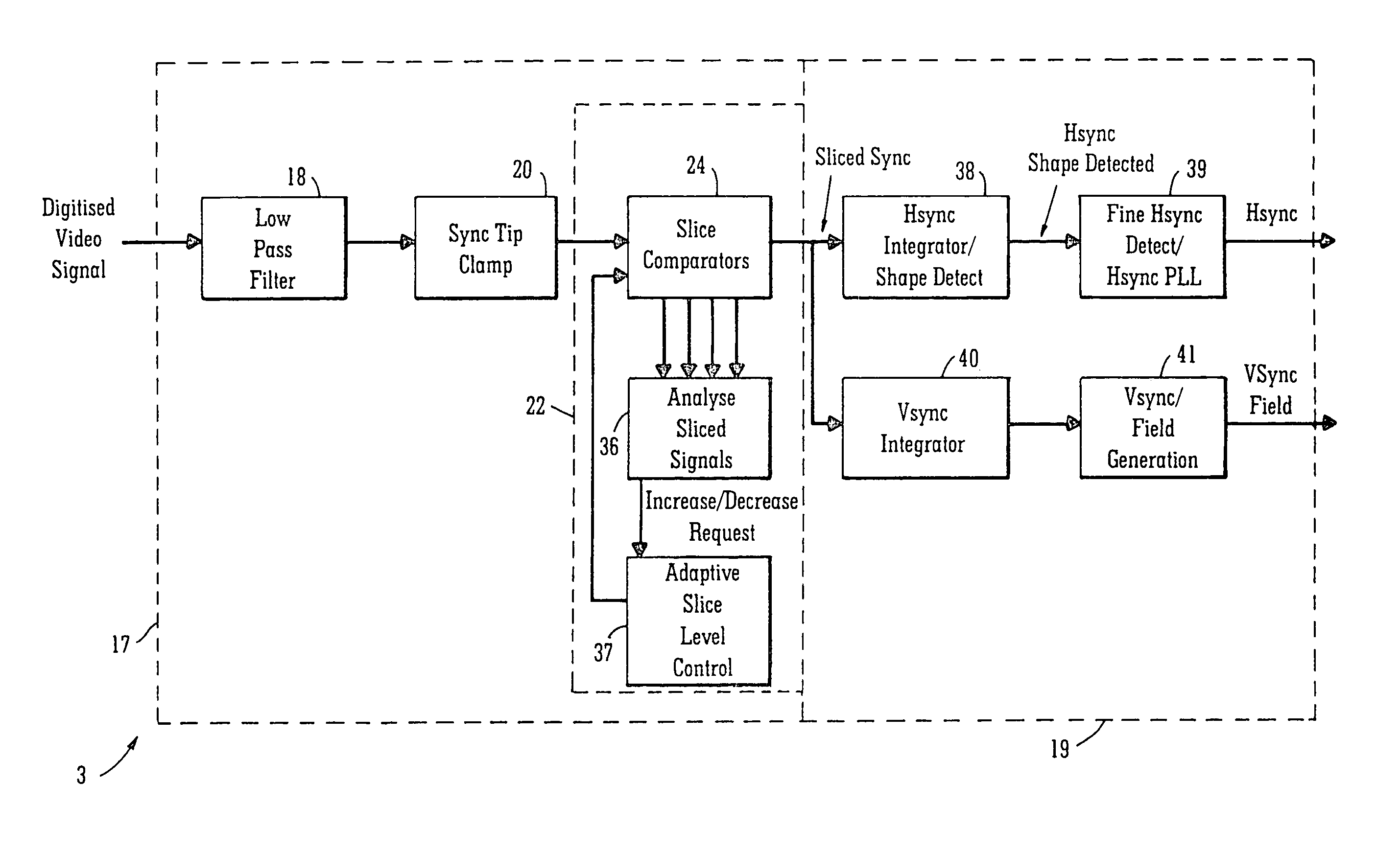
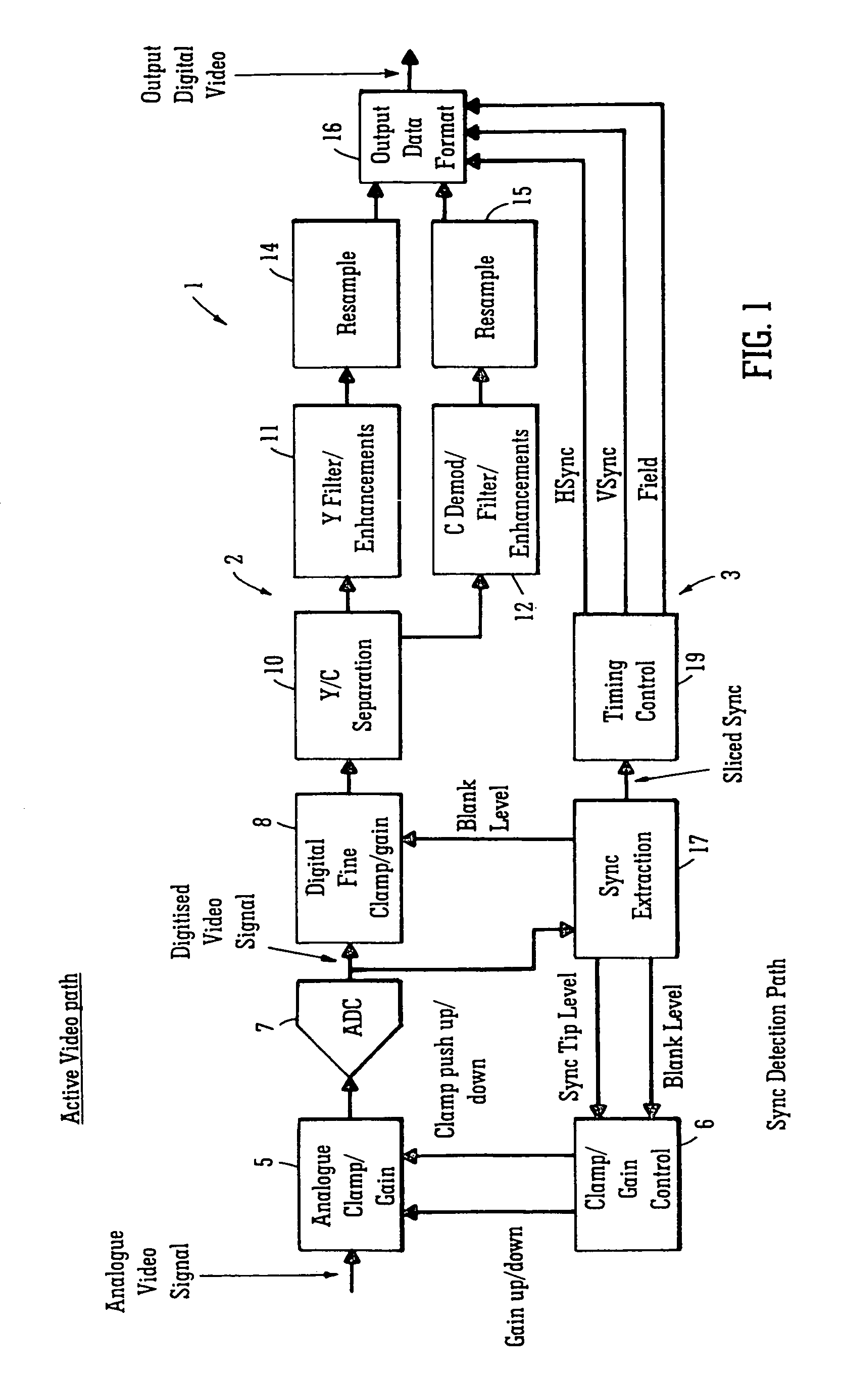
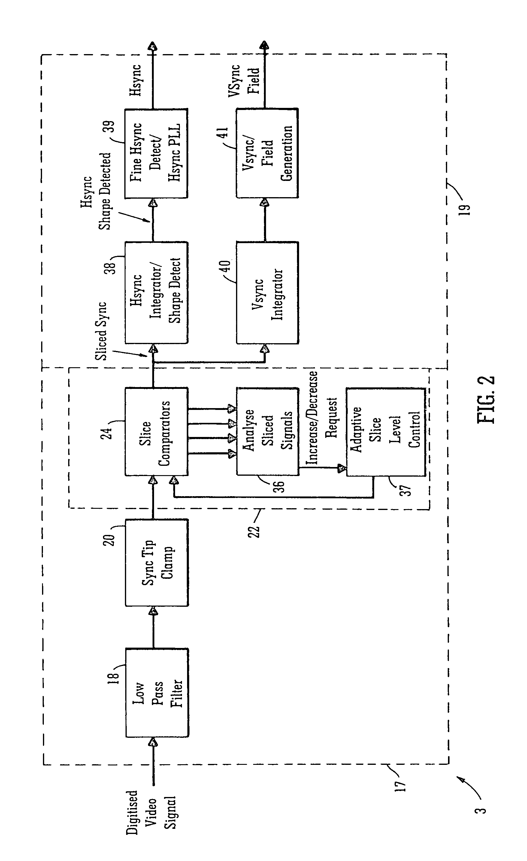
[0092]Referring to the drawings, and initially to FIGS. 1 to 4, there is illustrated a decoder according to the invention, indicated generally by the reference numeral 1, for decoding a video signal. The decoder 1 comprises an active signal processing and decoding circuit indicated generally by the reference numeral 2, and a synchronisation pulse signal recovery circuit also according to the invention indicated generally by the reference numeral 3 for implementing a method also according to the invention for deriving a synchronisation signal from the video signal, from which a horizontal sync signal of the video signal is recovered, and in turn a vertical sync signal and a field signal are also recovered. The sync signal recovery circuit 3 is provided in parallel with the active signal processing and decoding circuit 2, so that recovery of the horizontal and vertical sync signals and the field signal is carried out by the sync signal recovery circuit 3 effectively on the fly and sim...


PUM


Abstract

A method for deriving a synchronisation signal (35) from a video signal comprises tracking the blanking level (107) of the video signal with first and second slice level signals (26, 27) and tracking the sync tip level (110) of the horizontal sync signal (109) of the video signal with third and fourth slice level signals (28,29) for determining the blanking level (107) and the sync tip level (110). A value for an intermediate slice level signal (30) is computed from the first, second, third and fourth slice level signals (26, 27, 28, 29) so that the value of the intermediate slice level signal (30) lies approximately halfway between the blanking level (107) and the sync tip level (110). The video signal is compared with the intermediate slice level signal (30), and the synchronisation signal (35) is prepared from a logic signal by transitioning the logic signal from one of the logic high and logic low levels to the other of the logic high and logic low levels, each time the video signal transitions across the intermediate slice level signal (30).

Description

FIELD OF THE INVENTION[0001]The present invention relates to a method and a circuit for deriving a synchronisation signal from a video signal, and in particular, to a method and a circuit for deriving a synchronisation signal from a video signal which permits recovery of a horizontal sync signal from the video signal.BACKGROUND TO THE INVENTION[0002]Methods and circuits for recovering sync signals from a video signal are known. Such methods and circuits may be adapted for recovering the sync signals sequentially or simultaneously with active processing and decoding of the video signal. However, entire recovery of the sync signals sequentially with the active processing and decoding of the video signal, in general, militates against fast lock-in of the video signal. Accordingly, in order to minimise lock-In time, it is known to pass a video signal through two circuits in parallel, one of which carries out active signal processing and decoding of the video signal, and the other circui...

Claims


Application Information

Patent Timeline
Patent Type & Authority Patents(United States)
IPC IPC(8): H04N7/00H04N5/16H04N5/08H04N5/10
CPCH04N5/08H04N5/10H04N5/16
Inventor O'CONNELL, NIALL DANIEL
Owner ANALOG DEVICES INC
Why Eureka
Try Eureka