Air-to-air atmospheric heat exchanger for condensing cooling tower effluent

a technology of air-to-air and cooling tower, which is applied in the direction of carburetizing air, lighting and heating apparatus, and separation processes, etc. it can solve the problems of low lying fog, and moisture in the plume to freeze, so as to reduce the heat content of the air stream

Inactive Publication Date: 2008-02-12
SPX COOLING TECH
View PDF32 Cites 34 Cited by
  • Summary
  • Abstract
  • Description
  • Claims
  • Application Information

AI Technical Summary

Benefits of technology

[0021]In another aspect of the invention a method of reducing the moisture content of an air stream is provided wherein a first air stream having a flow rate between 10 and 80 pounds of dry air per square foot per minute (pda / ft2 / min) and a relative humidity at or above 90% is directed through a first set of passageways. A second air stream having a flow rate between 10 and 80pda / ft2 / min and a dry bulb temperature at least five Fahrenheit degrees below the second stream is directed through a second set of passageways. Each passageway of the first set of passageways being separated from at least one passageway of the second set of passageways by a thin heat conductive material. Heat from the second air stream is absorbed into the first air stream and water condensed out of the second air stream is captured. In yet another embodiment of the invention, a cooling tower is provided having a counterflow evaporative media and a water distribution system that distributes hot water over the counterflow evaporative media. A heat exchanger that absorbs heat from a first air stream into a second air stream is also provided, the heat exchanger having a first set of passageways and a second set of passageways. A fan in the cooling tower directs air through the counterflow evaporative media to create said first air stream and directs the first air stream, having a flow rate between 10 and 80 pounds of dry air per square foot per minute (pda / ft2 / min) and a relative humidity at or above 90%, through the first set of passageways. The fan also directs the second air stream having a flow rate between 10 and 80 pda / ft2 / min and a dry bulb temperature at least five Fahrenheit degrees below the second stream through the second set of passageways. Each passageway of the first set of passageways being separated from at least one passageway of the second set of passageways by a thin heat conductive material. A reservoir is provided for capturing water condensed out of the first air stream.
[0025]In still another aspect of the present invention, an apparatus for reducing the heat content of an air stream is provided. The apparatus includes a means for directing a first air stream through a first set of passageways of a generally diamond shaped heat exchanger. It also includes a means for directing a second air stream through a separate, second set of passageways of the generally diamond shaped heat exchanger. The apparatus further includes a means for transferring heat form the first air stream into the second air stream.
[0026]In still yet another embodiment of the present invention, a method for reducing the heat content of an air stream is provided, comprising the steps of: directing a first air stream through a first set of passageways of a generally diamond shaped heat exchanger; directing a second air stream through a separate, second set of passageways of the generally diamond shaped heat exchanger; and transferring heat from said first air stream into said second air stream.

Problems solved by technology

A recognized drawback to cooling towers, however, is that under certain atmospheric conditions a plume can be created by moisture from the heated water source evaporating into the air stream being carried out of the top of the cooling tower.
Where the cooling tower is very large, as in the case of power plants, the plume can cause low lying fog in the vicinity of the cooling tower.
The plume can also cause icing on roads in the vicinity of the cooling tower where colder temperatures cause the moisture in the plume to freeze.
As discussed in the patent, the separate heat exchanger reduces the efficiency of the cooling tower and thus should only be employed when atmospheric conditions exist in which a plume would be created by the cooling tower.
While the foregoing systems provide useful solutions to the wet cooling tower plume problem, they all require the construction of a complex and costly wet and dry air heat transfer mechanism.
Another recognized problem with cooling towers is that the water used for cooling can become concentrated with contaminates.
If chemicals are added to the cooling water to treat the water these chemicals can become highly concentrated which may be undesirable if released into the environment.
If seawater or waste water is used to replace the evaporated water, a common practice where fresh water is not available or costly, salts and solids in the water can also build up in the cooling water circuit As these contaminants become more concentrated they can become caked in between the thin evaporating sheets diminishing the towers cooling efficiency.
While this prevents the contaminants in the cooling tower water from becoming too concentrated, there may be environmental consequences to discharging water during the blowdown process.
A separate problem that has been noted is the desalination of sea water, and purification of other water supplies, to create potable drinking water.

Method used


Image

  • Air-to-air atmospheric heat exchanger for condensing cooling tower effluent
  • Air-to-air atmospheric heat exchanger for condensing cooling tower effluent
  • Air-to-air atmospheric heat exchanger for condensing cooling tower effluent

Examples


Embodiment Construction

[0061]Heat Exchanger Pack

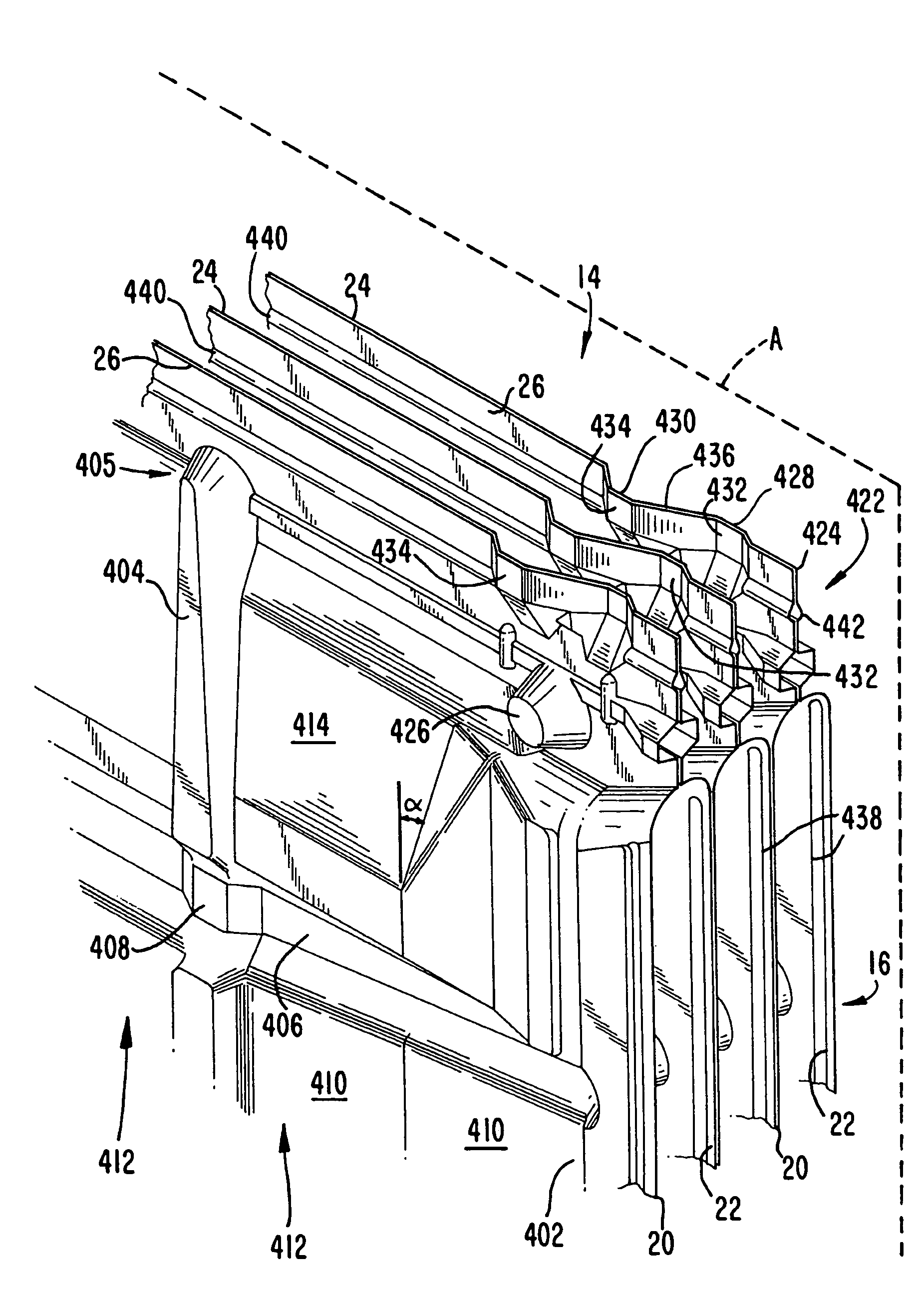
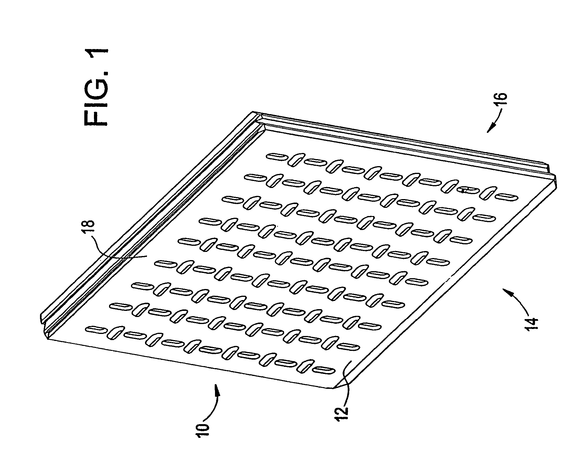
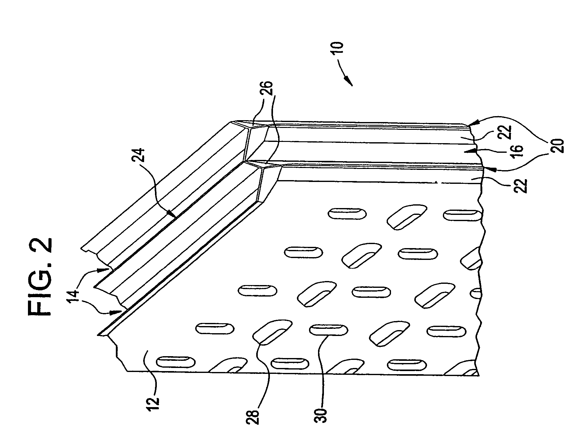
[0062]Referring now to the figures wherein like reference numerals indicate like elements, in FIG. 1 there is shown a vapor condensing heat exchanger pack 10. The heat exchanger pack 10 is constructed of thin sheets 12 that are bonded together to form a pack that has a first path 14 and a second path 16 for two different air streams. In a preferred embodiment, the two air streams enter the heat exchanger pack 10 at right angles to each other and are kept separate by the thin sheets 12.

[0063]The thin sheets 12 are a relatively thin synthetic resin material that are shaped to assist in condensing vapor from a heated water laden air stream passing through passageways 14 and transferring heat to a cool air stream passing through passageways 16. In a preferred embodiment, the material is 0.005 to 0.040 inches in thickness but is preferably 0.015 to 0.020 inches in thickness. The surface 18 may be textured to provide extended surface area presented to each of the ...


PUM

PropertyMeasurementUnit
angleaaaaaaaaaa
angleaaaaaaaaaa
angleaaaaaaaaaa

Abstract

A sheet for use in a heat exchange apparatus. The sheet includes a first vertical rib that extends in a first direction generally parallel to the vertical axis of the heat exchange apparatus, wherein said first vertical rib protrudes in a second direction out of the plane. The sheet also includes a second vertical rib that extends in the first direction along the sheet, substantially all the way between the first and second edges of the sheet generally parallel to the first vertical rib. The second vertical rib also protrudes in the second direction out of the plane. The sheet further includes a first horizontal rib that extends in a third direction along the sheet substantially all the way between the third and fourth edges of the sheet, wherein the first horizontal rib protrudes in a fourth direction opposite said second direction. The sheet additionally includes a second horizontal rib that extends in the third direction along the sheet substantially all the way between the third and fourth edges of the sheet generally parallel to the first horizontal rib. The second horizontal rib protrudes in a fourth direction opposite the second direction, into the plane and intersects said second vertical rib.

Description

PRIORITY[0001]This application is a continuation-in-part, and claims the benefit of, U.S. patent application Ser. No. 10 / 689,691, filed Oct. 22, 2003, now issued as U.S. Pat. No. 7,128,310, entitled AIR-TO-AIR ATMOSPHERIC HEAT EXCHANGER FOR CONDENSING COOLING TOWER EFFLUENT, which is a continuation-in-part of U.S. patent application Ser. No. 09 / 973,732, now issued as U.S. Pat. No. 6,663,694 and U.S. patent application Ser. No. 09 / 973,733 now issued as U.S. Pat. No. 6,663,087, each filed Oct. 11, 2001, both entitled AIR-TO-AIR ATMOSPHERIC HEAT EXCHANGER FOR CONDENSING COOLING TOWER EFFLUENT, the disclosures of which are incorporated herein by reference.FIELD OF THE INVENTION[0002]The present invention relates generally to water reclamation from cooling tower effluent or other heat rejection devices. More particularly, the present invention relates to method and apparatus for reclaiming water from cooling tower effluent to provide a source of clean water, reduce water consumption of t...

Claims


Application Information

Patent Timeline
Patent Type & Authority Patents(United States)
IPC IPC(8): B01D53/26F28C1/14F28C1/16F28D9/00F28F3/00
CPCF28C1/14F28D9/0037F28F25/00F28F2025/005Y10S261/11Y10S261/77Y10S165/356Y10S261/03Y10S165/90Y10S165/185Y10S165/384Y10S165/382Y10S165/357Y10S165/182Y02B30/70
Inventor MOCKRY, ELDON F.STRATMAN, JASONYANG, JIDONGJOHNSON, MARK ANTHONY
Owner SPX COOLING TECH
Why Eureka
Try Eureka