Device for electrostatic discharge protection

a technology of electrostatic discharge and protection device, which is applied in the direction of semiconductor devices, semiconductor/solid-state device details, electrical apparatus, etc., can solve the problems of limited electrostatic discharge immunity under reverse bias voltage, unrecoverable permanent damage, and frail integrated circuits, so as to maintain the performance of the device and save the layout area of the integrated circuit.

Inactive Publication Date: 2008-02-12
WINBOND ELECTRONICS CORP
View PDF16 Cites 5 Cited by
  • Summary
  • Abstract
  • Description
  • Claims
  • Application Information

AI Technical Summary

Benefits of technology

[0007]It is therefore an object of the invention to provide a device for electrostatic discharge protection to maintain the performance of the device for electrostatic discharge protection and save the layout area of the integrated circuit.

Problems solved by technology

Integrated circuit is frail and easy to be damaged during electrostatic discharge.
Even though it maybe just a minor and temporary feeling for human body during electrostatic discharge, the damage resulting from the electrostatic discharge is unrecoverable and permanent.
The conventional device for electrostatic discharge protection shown in FIGS. 1 and 2 has a drawback, which is the limited electrostatic discharge immunity under a reverse bias voltage.
Therefore, it is a dilemma of maintaining the performance of the device for electrostatic discharge protection or saving the layout area of the integrated circuit being protected, and a compromise must be made between the performance of the device for electrostatic discharge protection and the layout area of the integrated circuit being protected.

Method used


Image

  • Device for electrostatic discharge protection
  • Device for electrostatic discharge protection
  • Device for electrostatic discharge protection

Examples


Embodiment Construction

[0018]It is to be understood and appreciated that the circuit described below do not cover a complete circuit layout. The present invention can be practiced in conjunction with various circuit techniques that are used in the art, and only so much of the commonly practiced techniques are included herein to provide an understanding of the present invention.

[0019]The present invention will be described in detail with reference to the accompanying drawings. It should be noted that the drawings are in greatly simplified form and they are not drawn to scale. Moreover, dimensions have been exaggerated in order to provide a clear illustration and understanding of the present invention.

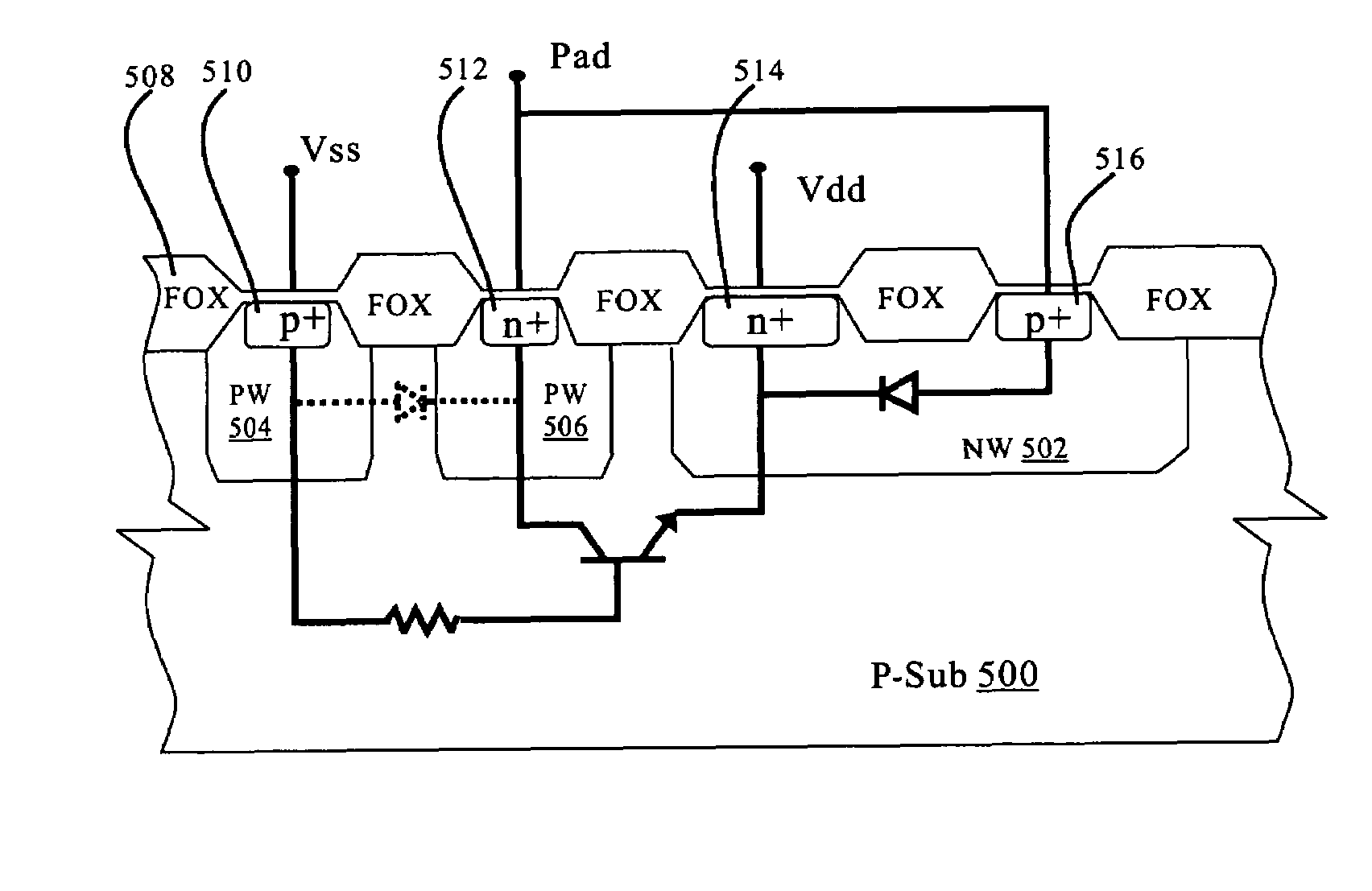
[0020]In one embodiment of the invention, the device for electrostatic discharge for protection of the invention further includes an N+ diffusion ring into a P well, wherein the N+ diffusion ring connects to a bond pad between the cathode of a diode and a P+ guard ring to for a parasitic lateral npn bipolar tr...


PUM


Abstract

A device for electrostatic discharge (ESD) protection is disclosed. The device for electrostatic discharge protection includes a lateral bipolar transistor and a diode. The semiconductor transistor has an emitter, a base and a collector electrically connected to a first power line (such as Vdd), a second power line (such as Vss) and a bond pad of an integrated circuit respectively. The diode has an n electrode and a p electrode electrically connected to the first power line and the bond pad respectively.

Description

BACKGROUND OF THE INVENTION[0001]1. Field of the Invention[0002]The present invention relates to a device for electrostatic discharge (ESD) protection, and more particularly to a device for electrostatic discharge (ESD) protection with upgraded electrostatic discharge immunity when a reverse bias voltage is applied.[0003]2. Description of the Related Art[0004]Integrated circuit is frail and easy to be damaged during electrostatic discharge. Even though it maybe just a minor and temporary feeling for human body during electrostatic discharge, the damage resulting from the electrostatic discharge is unrecoverable and permanent. Electrostatic discharge could be present any moment during the manufacture process of integrated circuit chip, most of electrostatic discharge are present during the processes of forming integrated circuits on wafers or the stage of integrated circuit package.[0005]In order to keep integrated circuits from being damaged by electrostatic discharge, additional de...

Claims


Application Information

Patent Timeline
Patent Type & Authority Patents(United States)
IPC IPC(8): H01L23/62H01L29/00H01L29/72H01L29/74H01L31/111
CPCH01L27/0259
Inventor TSENG, JEN-CHOU
Owner WINBOND ELECTRONICS CORP
Why Eureka
Try Eureka