Best-focus estimation by lateral scanning

a scanning array microscope and best focus technology, applied in the field of microscopy, can solve problems such as interference effects that modulate intensity, and achieve the effect of improving image quality

Inactive Publication Date: 2008-02-12
DMETRIX INC
View PDF11 Cites 26 Cited by
  • Summary
  • Abstract
  • Description
  • Claims
  • Application Information

AI Technical Summary

Benefits of technology

[0011]U.S. Pat. No. 6,449,048 describes an interferometer where the sample surface is scanned laterally and continuously with respect to the optical axis of the interferometric objective. The resulting scan produces a profile of the entire sample surface in a single pass, eliminating the need to repeat interferometric measurements as the interferometer's objective is placed over different sections of the sample. The objective is tilted, so that the sample surface is placed at an angle with respect to the maximum coherence plane of the instrument. By moving the sample laterally, at an angle, substantially through the focal plane at a set distance from the objective on the objective's optical axis, rather than vertically along the optical axis, different parts of the sample surface intersect the maximum coherence plane at different times as the sample object passes through the coherence plane, the precise time depending on the profile of the surface.
[0012]When the optical path difference (OPD) of a point on the object's surface is greater than the coherence length of the light source, the intensity of the light reflected from this point does not produce interference fringes. However, interference effects modulate the intensity the same way as in a regular vertical-scanning interferometry (VSI) procedure when the object point enters the zone of coherence. As the object moves along the direction of scanning, because of the tilt of the objective's optical axis with respect to the scanning plane, the sample's motion includes an axial component relative to the objective. Therefore, the lateral scanning motion produces an OPD variation like the vertical scan in a conventional system. As a result, light-intensity data can be acquired continuously as the test surface is scanned. Thus, according to the main objective of the invention described in U.S. Pat. No. 6,449,048, lateral scanning eliminates the need for taking multiple measurements over the sample surface and for stitching sub-sets of data to form a larger composite image.
[0018]The information acquired during such a pre-scan of the sample surface under either embodiment of the invention is used to develop a map of best-focus positions for each point on the surface. This map is then advantageously utilized to improve the quality of the images acquired during the subsequent measurement scan of the sample. In order to implement this feature of the invention, the sample stage (or, equivalently, the array microscope) is coupled to a support mechanism that allows its height adjustment as well as its rotation both along the sample's width and length (first and second dimensions, respectively, in FIG. 1). As the sample is scanned under the array microscope, the relative position of the two is adjusted by lifting or lowering the sample and by rotating it along both axes as necessary to optimize the focal position of each point of the surface as it passes through the field of view of a corresponding miniaturized microscope. The best-focus map developed according to the invention is tracked during the scan using conventional robotics apparatus.

Problems solved by technology

However, interference effects modulate the intensity the same way as in a regular vertical-scanning interferometry (VSI) procedure when the object point enters the zone of coherence.

Method used


Image

  • Best-focus estimation by lateral scanning
  • Best-focus estimation by lateral scanning
  • Best-focus estimation by lateral scanning

Examples


Embodiment Construction

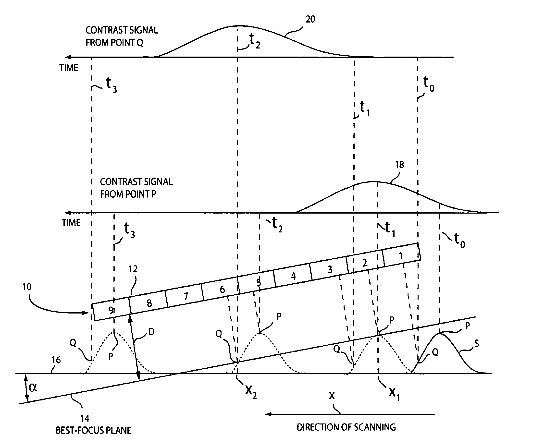
[0030]The invention is based on the realization that the best-focus position of a sample being imaged by an array microscope can be estimated by continuously scanning the sample surface along a plane that is tilted with respect to the array's best-focus plane. By scanning the sample across the tilted best-focus plane of the array microscope, the axial positions of points being imaged under best-focus conditions can be directly identified as a result of a single scan. If required, the best-focus position of the other points on the surface can be estimated by interpolation or other technique. Thus, with a single measurement it is possible to generate data that can then be used advantageously to improve the image quality during a subsequent measurement scan.

[0031]As used herein, the term “microscope” is used with reference to both the array microscope and the individual miniaturized microscopes within the array, and it is assumed that the distinction will be apparent to those skilled i...


PUM


Abstract

The sample stage of an array microscope is tilted in the scanning direction such that the best-focus plane of the array microscope intersects the surface of the sample during the scan. As a result of the tilt, the distance from the sample surface of each miniaturized microscope spanning the array varies from point to point on the surface. Accordingly, the best focal distance for each such point on the sample surface is identified by tracking the quality of its focus as the sample surface travels across the rows of microscopes in the array. Best focus may be detected using any known technique, such as by measuring spatial frequency content and recording the scan position corresponding to maximum mid-range frequency content. This information is used to develop a best-focus axial-position map for use while performing a subsequent measurement scan.

Description

BACKGROUND OF THE INVENTION[0001]1. Field of the Invention[0002]This invention is related in general to the field of microscopy. In particular, it relates to a method and apparatus for finding the best-focus position of a scanning array microscope that includes a plurality of optical imaging elements with respective optical axes.[0003]2. Description of the Related Art[0004]The object to be imaged by a microscope is typically located at the object plane by being placed on a substrate that is, in turn, positioned on a stage of the microscope that can be moved laterally with respect to the optical axis of the lens system. The stage may be motorized so that this movement may be automated or controlled by a computer. Moreover, the image plane may be provided with a camera or other imaging device for recording the image, or for monitoring the image under the same computer control.[0005]In addition to being characterized by its numerical aperture, an imaging lens system is also characteriz...

Claims


Application Information

Patent Timeline
Patent Type & Authority Patents(United States)
IPC IPC(8): G06K9/00G02B21/24
CPCG02B21/244Y10S128/922
Inventor OLSZAK, ARTUR G.
Owner DMETRIX INC
Why Eureka
Try Eureka