Acoustic noise reduction using fan speed control

a technology of fan speed control and acoustic noise reduction, which is applied in the direction of motor/generator/converter stopper, dynamo-electric converter control, ventilation system, etc., can solve the problems of low fan speed and associated noise level, and achieve the effect of reducing aerodynamic acoustic noise, reducing maximum error, and dampening controller response to error variation

Active Publication Date: 2008-02-19
CIENA
View PDF5 Cites 25 Cited by
  • Summary
  • Abstract
  • Description
  • Claims
  • Application Information

AI Technical Summary

Benefits of technology

[0011]Advantages of the present invention include provision of a fan speed directly related to electronics temperature which inherently accounts for higher ambient temperatures, enclosure altitude, electronics power consumption, air filter clogging, or reduced airflow due to other causes. In addition, card-specific temperature set points yield a lowest fan speed and associated noise level based on electronic circuit pack fill within the enclosure.
[0013]Advantageously, the apparatus may operate so as to poll the plurality of temperature detecting means at intervals. Conveniently, a hysteresis temperature band may be used so that a current fan speed is maintained if a current maximum error is within the hysteresis temperature band of the maximum error of a previous poll. A result is a constant fan speed for cyclical variations in ambient temperature having an amplitude less than the specified hysteresis, due for example, to on / off cycling of an air conditioning system. Also advantageously, the maximum error may be filtered, conveniently by an exponentially weighted filter using in part the maximum error of the previous polls, so as to dampen the response of the controller to error variations.
[0014]In accordance with another aspect of the present invention there is provided a method for reducing aerodynamic acoustic noise generated by at least one cooling fan for an electronics equipment enclosure, having the steps of sampling a plurality of temperature detecting means disposed at a plurality of locations within the electronics equipment enclosure, each of said plurality of temperature detecting means having an associated setpoint temperature. Then, determining an error value for each of the plurality of temperature detecting means, the error value being the difference between a temperature detected at that temperature detecting means and the associated setpoint temperature. Next, determining the maximum error among the plurality of error values; and then setting the operating speed of the at least one cooling fan in response to the maximum error.

Problems solved by technology

In addition, card-specific temperature set points yield a lowest fan speed and associated noise level based on electronic circuit pack fill within the enclosure.

Method used


Image

  • Acoustic noise reduction using fan speed control
  • Acoustic noise reduction using fan speed control
  • Acoustic noise reduction using fan speed control

Examples


Embodiment Construction

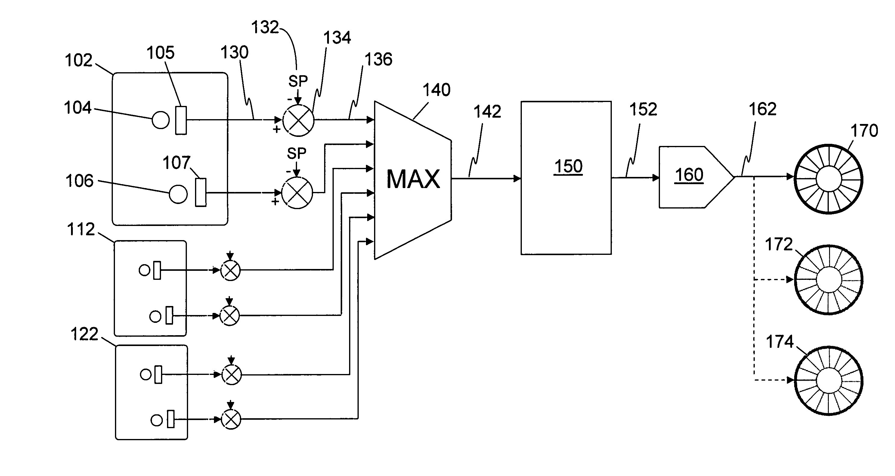
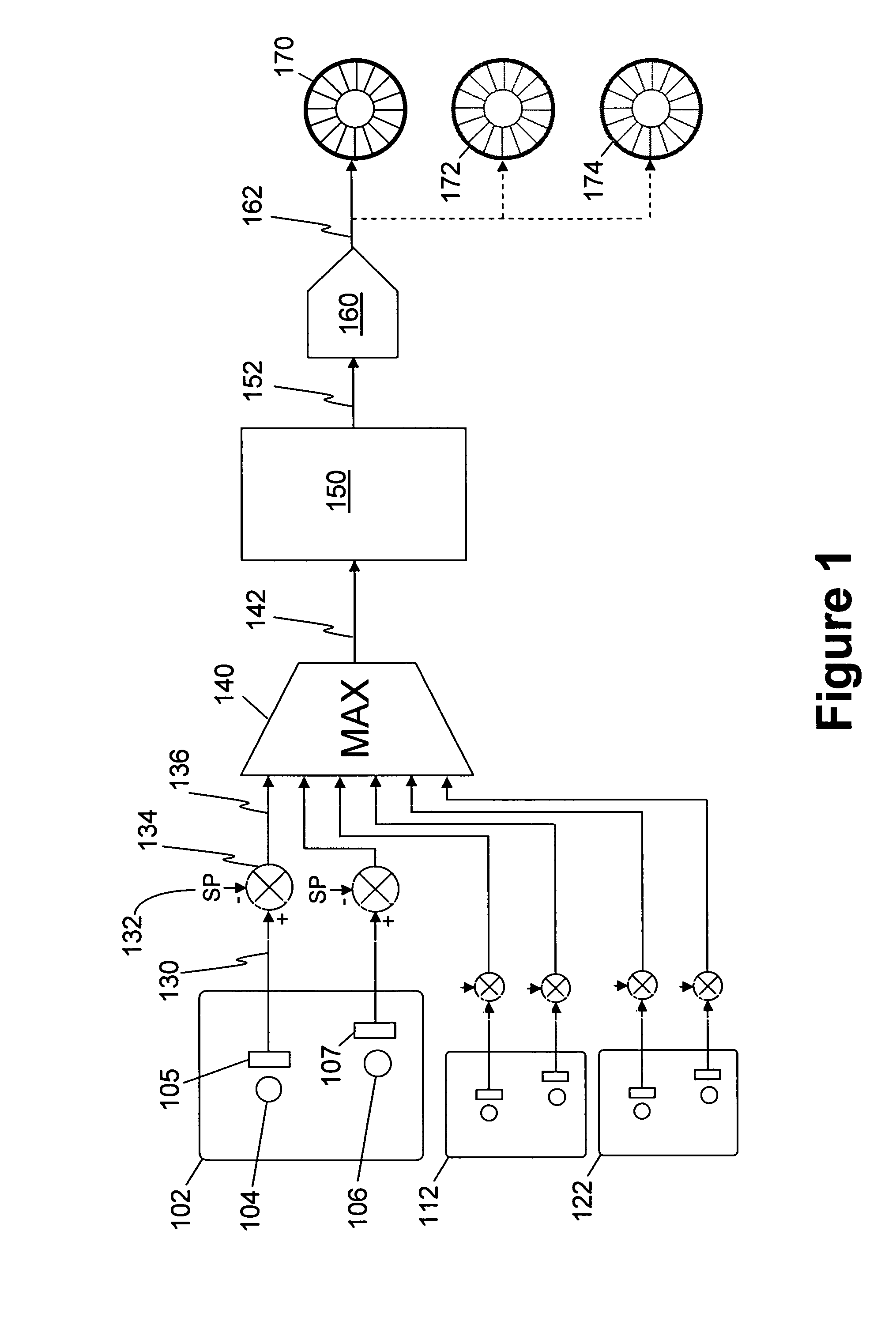
[0022]Referring to FIG. 1 there may be seen a fan control system according to an embodiment of the invention. Electronic equipment circuit board 102 has temperature sensitive electronic components 104 and 106. In close proximity to components 104 and 106 are respective temperature measuring devices 105 and 107. These devices typically comprise temperature measurement integrated circuits which provide a digital output indicating the temperature. A temperature resolution of 0.5° C. provides a satisfactory performance. The temperature output of measurement device 105 is communicated at 130 to a differencer 134. Communication 130 may be a dedicated signalling line or a common bus. Differencer 134 also accepts setpoint value 132 and operates by determining the difference between the temperature communicated at 130 and setpoint value 132 to generate an error value 136. The error value 136 is provided to a maximum error determining means 140.

[0023]As may be seen in FIG. 1, further electron...


PUM


Abstract

A method and apparatus is disclosed for acoustic noise reduction using fan speed control. The acoustic noise reduction using fan speed control includes a plurality of temperature detectors disposed at a plurality of locations within an electronics equipment enclosure, each detector having an associated setpoint temperature. An error value is determined for each temperature detector, the error consisting of the difference between the detected temperature and the associated setpoint temperature. The maximum error among all error values is then identified and the operating speed of a cooling fan in is set in response to this maximum error. Advantages include providing a fan speed directly related to electronics temperature which inherently accounts for higher ambient temperatures, enclosure altitude, electronics power consumption, and air filter clogging. The acoustic noise reduction using fan speed control is particularly useful for overcoming the need to overcompensate fan speed, thereby resulting in higher than necessary noise levels in order to accommodate worse-case conditions known in the art.

Description

FIELD OF THE INVENTION[0001]The present invention relates to acoustic noise reduction using fan speed control and is particularly concerned with reducing cooling air flow velocities while ensuring that thermally critical areas do not overheat as a result of the reduced flow.BACKGROUND OF THE INVENTION[0002]As the functionality and bandwidth of communications networks continues to increase, the power dissipation of the network elements continues to rise concurrently. This has resulted in the use of larger forced-air thermal management systems to cool this equipment which consume more power and generate increasing levels of acoustic noise. These issues have become an area of concern for some customers.[0003]Aerodynamic noise in a fan-cooled enclosure for electronics constitutes a difficult to eliminate noise source since it is generated by a material flow necessary for cooling the electronics. Reduction of flow rates carries the associated risk of inadequate cooling resulting in equip...

Claims


Application Information

Patent Timeline
Patent Type & Authority Patents(United States)
IPC IPC(8): F24F7/00G05D23/00H02H7/08H02P7/00H05K7/20
CPCH05K7/20209
Inventor CURRIE, THOMASATKINSON, JOHN CLAYTONNICOLICI, MARKOPATEL, AMRISHMCFARLANE, KEN
Owner CIENA
Why Eureka
Try Eureka