Cathode layer structure for a solid polymer fuel cell and fuel cell incorporating such structure

a solid polymer fuel cell and cathode layer technology, which is applied in the direction of cell components, electrochemical generators, coatings, etc., can solve the problem of slow kinetics of the oxygen reduction reaction, and achieve the effect of reducing the tendency of carbonation and fast orr kinetics

Inactive Publication Date: 2008-02-19
POWERCELL SWEDEN AB
View PDF5 Cites 14 Cited by
  • Summary
  • Abstract
  • Description
  • Claims
  • Application Information

AI Technical Summary

Benefits of technology

[0006]Thus, in view of the drawbacks with prior art fuel cells, i.e. the acidic medium causing a reduced ORR, the object of the invention is to provide a cathode layer structure that combines the advantages with fast ORR kinetics in alkaline medium, with a reduced tendency of carbonating, normally present in fuel cells working with alkaline media.

Problems solved by technology

However, the slow kinetics of the oxygen reduction reaction (ORR) at the cathode side is still the main source of losses in a fuel cell using a proton conducting membrane.

Method used


Image

  • Cathode layer structure for a solid polymer fuel cell and fuel cell incorporating such structure
  • Cathode layer structure for a solid polymer fuel cell and fuel cell incorporating such structure
  • Cathode layer structure for a solid polymer fuel cell and fuel cell incorporating such structure

Examples


example 1 (

STATE OF THE ART)

[0062]Step I: Preparation of an ink consisting of Pt supported catalyst and solubilized proton conducting polymer which is in Na+ or TBA+ form. Proton conducting polymers of NAFION™ type perfluorinated ionomers in Na+ form tolerate higher temperatures that enables the hot pressing step. The solubilized proton conducting polymer imparts ion conductivity to the catalyst layer but also acts as a binder and imparts robustness, and integrity to the layer.[0063]Step II: Mixing the ink thoroughly for several hours (typically 20-40 wt % Pt on C, 5 wt % NAFION™ perfluorinated ionomers)[0064]Step III: Different possibilities to apply ink on the membrane[0065]a) the “decal” process (i.e. ink is cast onto TEFLON® fluoropolymer sheets and then transferred to membrane in Na+ form by hot pressing)[0066]b) the ink is directly cast onto the membrane in Na+ form[0067]c) the ink is sprayed onto the membrane in Na+ form[0068]Step IV: Hot pressing of the membrane electrode assembly (MEA...

example 2 (

CATHODE LAYER STRUCTURE ACCORDING TO THE INVENTION)

[0070]One fundamental aspect to be noted, is that it will not be possible to ion-exchange a catalyst layer made of a mixture of hydroxide conducting polymer and proton conducting polymer.

[0071]As results obtained in our laboratory have shown, temperatures as high as 200° C. are not necessary to impart long term stability or good performance, and ion exchanging the acid-and-base catalyst layer can simply be avoided without drawback.

[0072]Another possibility is to use types of polymers that would tolerate the hot pressing conditions under proton and hydroxide form directly. Then no ion exchanging is needed either.

[0073]Both possibilities are described now.[0074]Step I: Preparation of ink consisting of supported catalyst and solubilized OH− (anion) conducting polymer in OH− form, using a first solvent (i.e. a solvent suitable for dissolving the OH− conducting polymer. Examples are an aqeous solution of lower alcohols, such as methanol,...


PUM

PropertyMeasurementUnit
currentaaaaaaaaaa
thickaaaaaaaaaa
diameteraaaaaaaaaa

Abstract

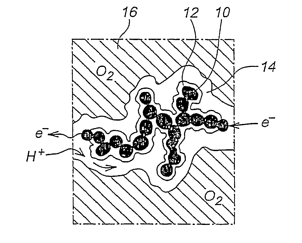
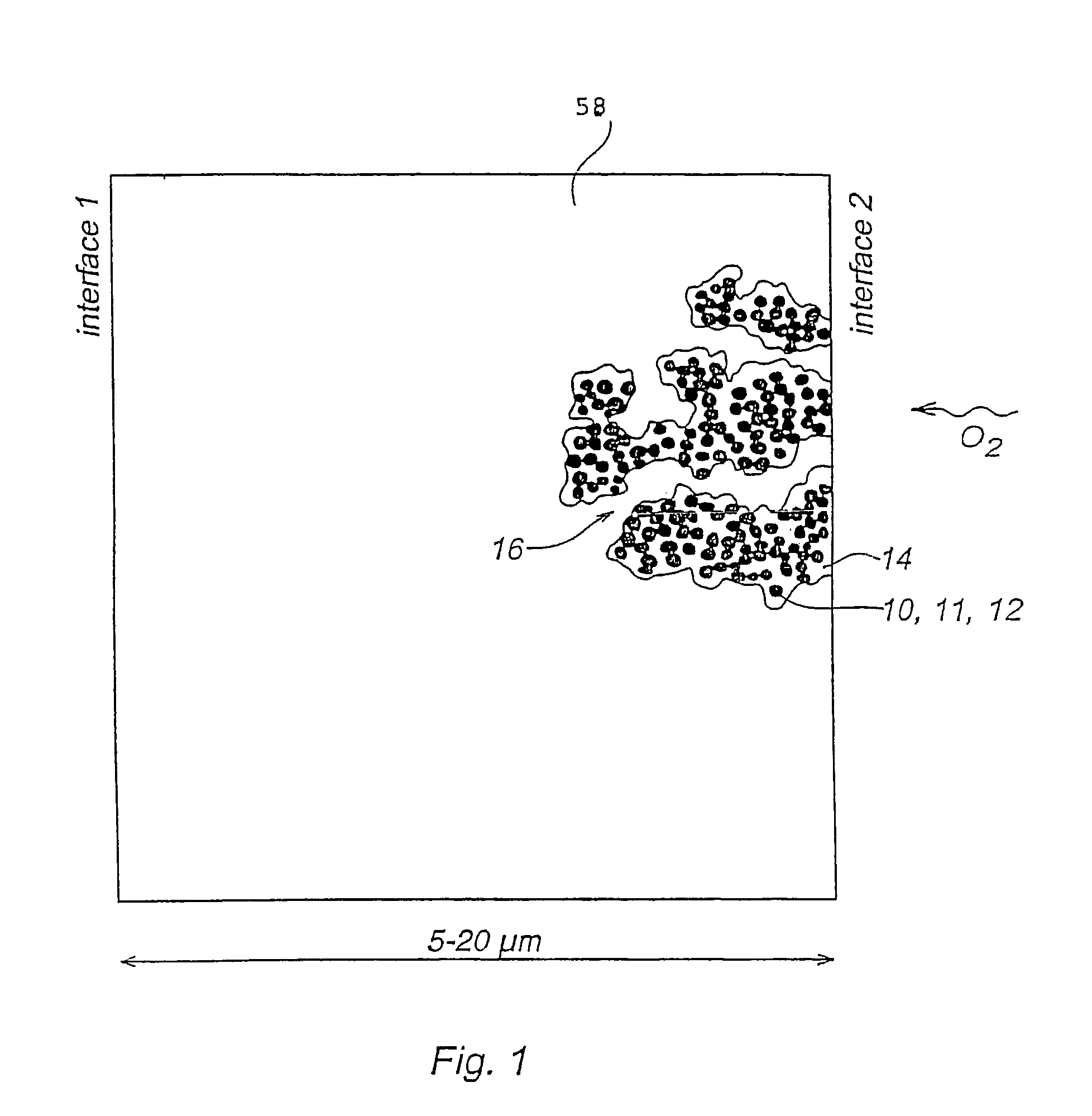
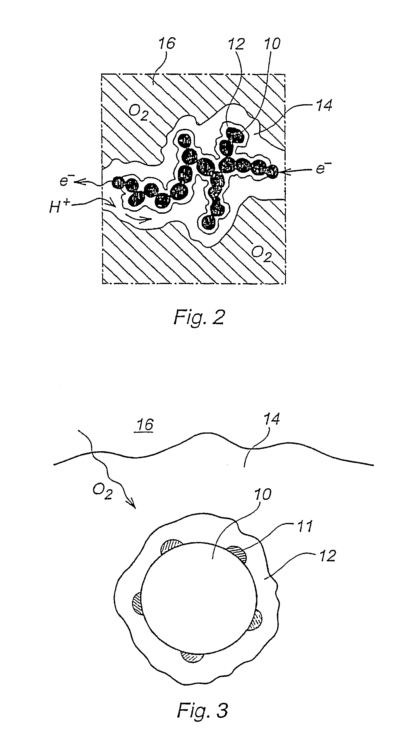
A cathode layer structure for a solid polymer fuel cell is disclosed. It comprises a composite cathode layer (48) of catalyst (11), anion ion conducting polymer (12) and cation conducting polymer (14). The interface between the anion ion conducting polymer (12) and the cation conducting polymer (14) is located entirely within the cathode layer (48). In particular the catalyst (11) is embedded in the anion conducting polymer (12), and the cation conducting polymer (14) encloses regions of the anion conducting polymer (12).

Description

[0001]The present invention relates to solid polymer fuel cells in general, and to a cathode layer structure for such fuel cells in particular.BACKGROUND OF THE INVENTION[0002]Solid polymer fuel cells (SPFC) generally comprise a cathode structure and an anode structure separated by a proton conducting membrane. These cells are about to be commercialized both for mobile and stationary applications. Reduction of Pt catalyst amount and development of thinner membranes more adapted to fuel cell application have increased the energy density and decreased the cost of solid polymer fuel cells.[0003]However, the slow kinetics of the oxygen reduction reaction (ORR) at the cathode side is still the main source of losses in a fuel cell using a proton conducting membrane. In order to have a current of e.g. 50 mA, the corresponding potential loss at cathode side is typically 450 mV with state of the art electrodes.[0004]It is well known that the kinetics of the ORR is faster in alkaline medium t...

Claims


Application Information

Patent Timeline
Patent Type & Authority Patents(United States)
IPC IPC(8): H01M4/88H01M4/86H01M4/92H01M4/96H01M8/10
CPCH01M4/8857H01M4/886H01M4/8882H01M4/8896H01M4/92H01M4/926H01M4/96H01M8/1004H01M4/921Y02E60/521Y02E60/50
Inventor JAOUEN, FREDERIC
Owner POWERCELL SWEDEN AB
Why Eureka
Try Eureka