Confocal microscopy

a technology of confocal optics and microscopes, applied in the field of confocal microscopy, can solve the problems of large and expensive, limited depth resolution of apparatuses, and inability to utilize confocal optics for microscopic imaging

Inactive Publication Date: 2008-02-19
THE GENERAL HOSPITAL CORP
View PDF31 Cites 75 Cited by
  • Summary
  • Abstract
  • Description
  • Claims
  • Application Information

AI Technical Summary

Benefits of technology

[0007]It is another object of the present invention to provide an improved confocal microscope system for imaging tissue using a synthesized light source to produce a beam having different wavelengths, in which the synthesized light source combines beams from multiple light sources producing light at each of the different wavelengths.
[0008]It is another object of the present invention to provide an improved confocal microscope system for imaging which can use low NA confocal optics, such as below 0.7, while achieving imaging performance in terms of axial resolution equivalent to prior art confocal microscope systems using higher NA confocal optics, such as between 0.7 and 0.9.

Problems solved by technology

One problem with using optics providing NA values about this range is that they are large and expensive, particularly for the objective lens which focuses light into and collects light from the tissue, and are very sensitive to aberrations, such as introduced by the object being imaged.
However, this apparatus is limited in depth resolution and does not utilize confocal optics for microscopic imaging.
Other optical systems have used multiple wavelengths of light, but are limited to generating interference patterns for visualizing fringes characterizing the surface of objects, such as shown in U.S. Pat. No. 5,452,088, which describes a multi-mode laser apparatus for eliminating background interference, and U.S. Pat. No. 4,632,554, which describes a multiple frequency laser interference microscope for viewing refractive index variations.
Such interferometric-based optical systems have no confocal optics or heterodyne detection, nor do they provide imaging within a tissue sample.
A confocal microscope using multiple wavelengths of light has been proposed in U.S. Pat. No. 4,965,441, but this microscope is limited to focusing at different altitudes for surface examination of an object and does not have heterodyne detection.

Method used


Image

  • Confocal microscopy
  • Confocal microscopy
  • Confocal microscopy

Examples


Embodiment Construction

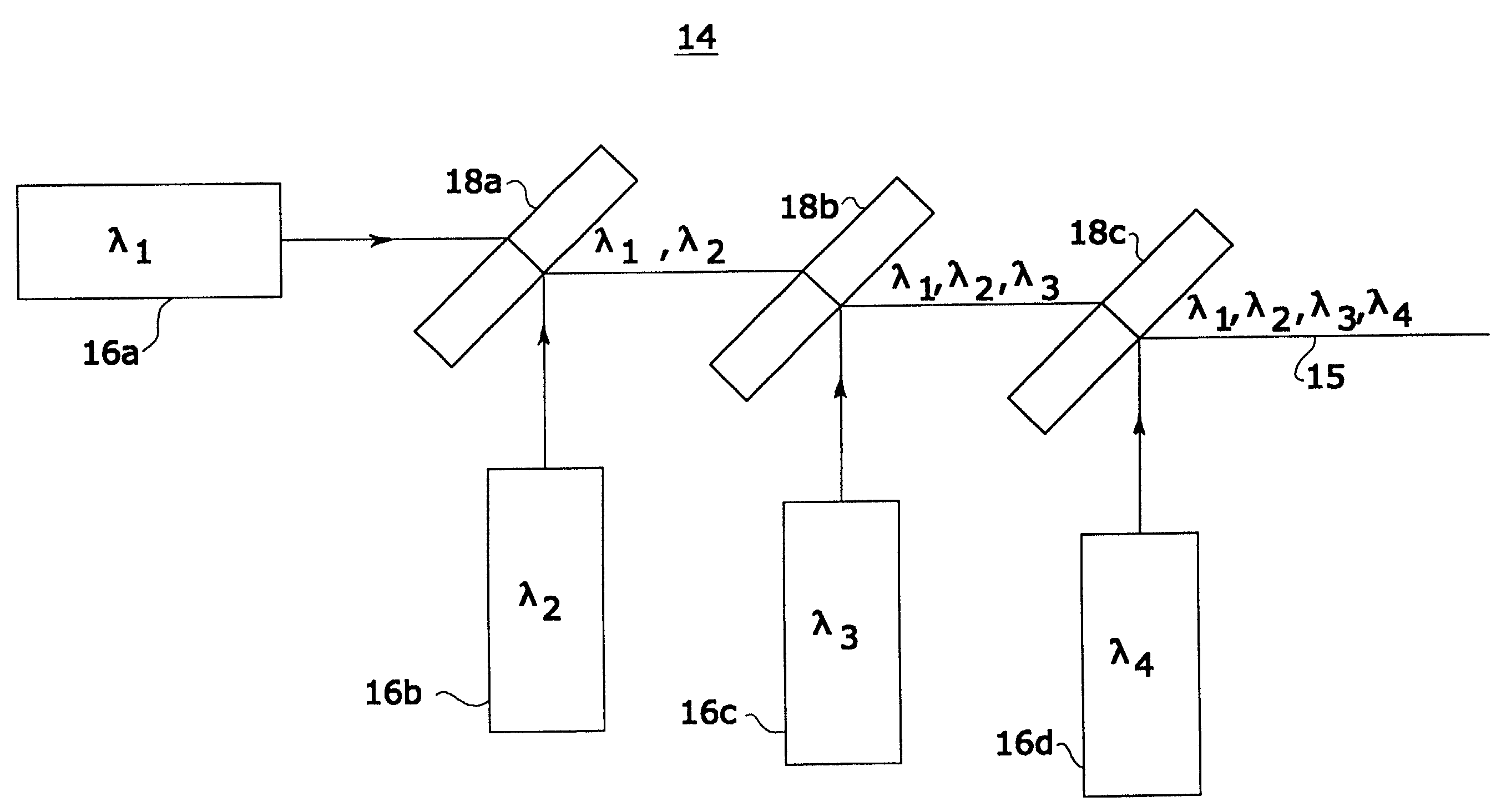
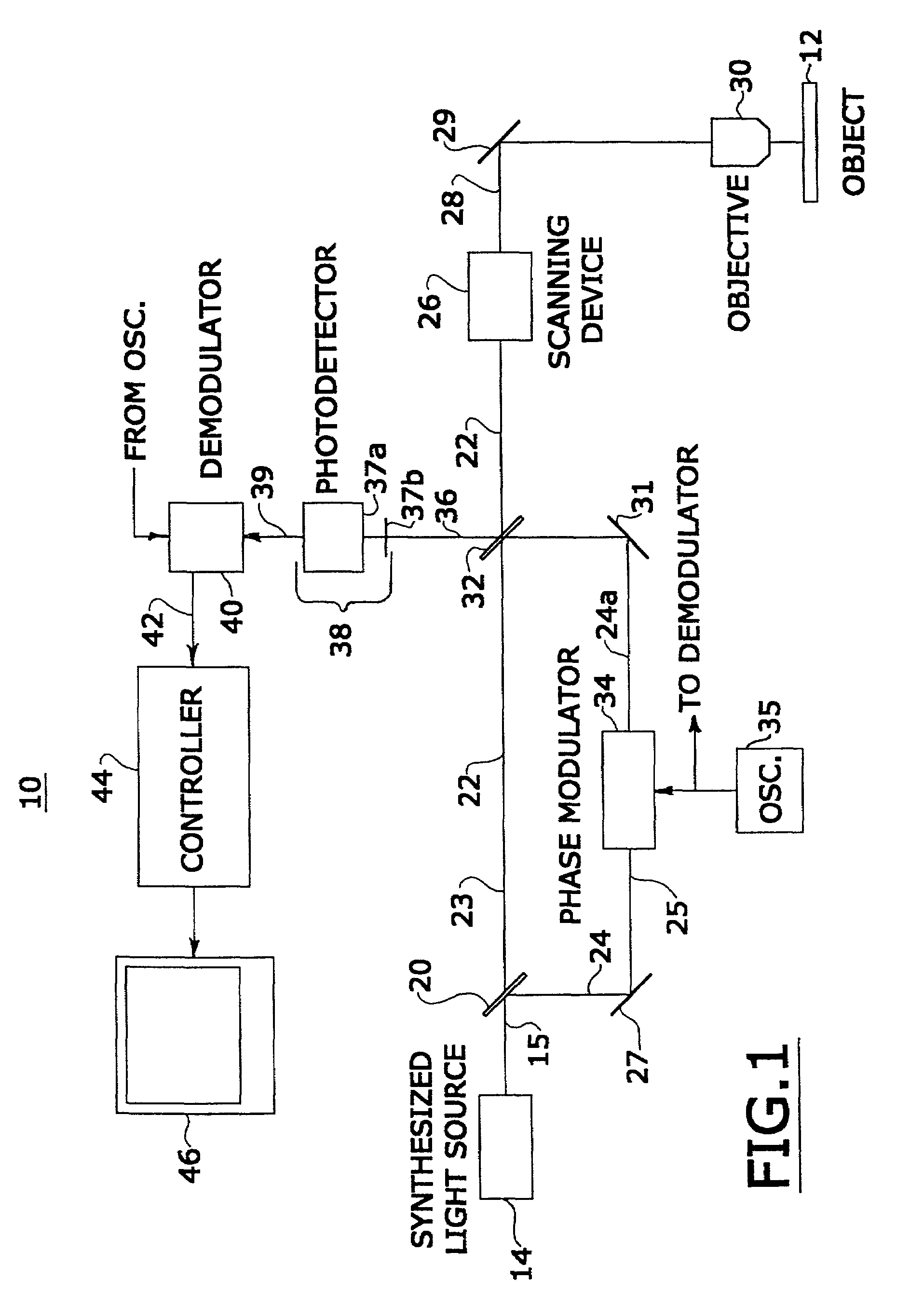
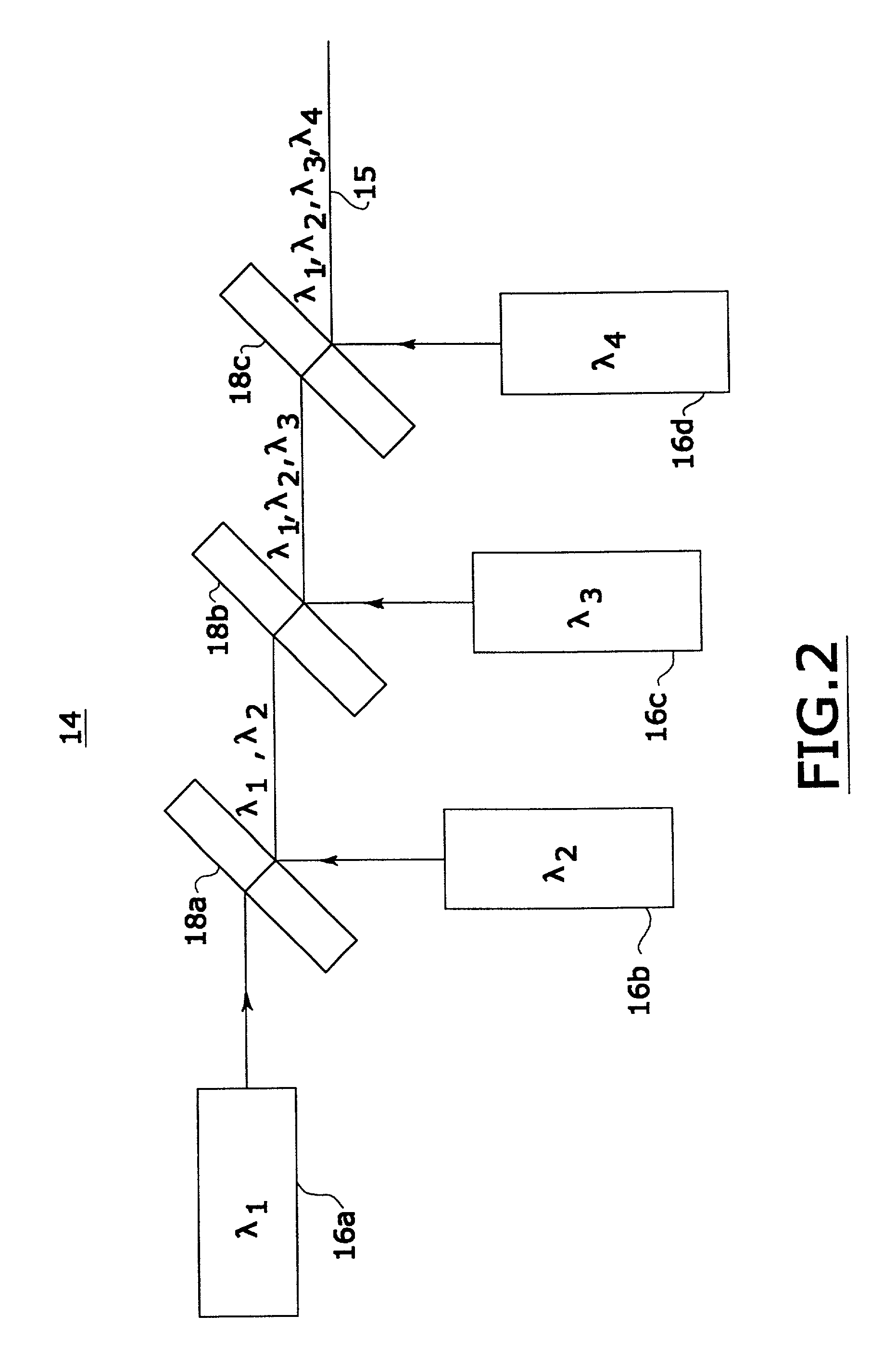
[0017]Referring to FIG. 1, a confocal microscope system 10 is shown for producing images of sections of an object 12, such as a tissue sample or in-vivo tissue of patient, below the surface of the object. System 10 includes a synthesized light source 14 providing a single beam 15 having several, different wavelengths of light. Synthesized light source 14 includes a number (N) of multiple light sources each providing light beams at a different wavelength, which are combined into a single beam 15. Beam 15 thus represents light that has a coherence function with narrow peaks depending on the wavelengths (or frequencies) of each of the multiple light sources of synthesized light source 14. The wavelengths of the light sources of the synthesized light source are selected to be transparent to object 12 to a particular depth from the object's surface. For tissue, such transparency occurs in the infrared spectrum of light.

[0018]An example of synthesized light source 14 with four light sourc...


PUM


Abstract

An improved confocal microscope system is provided which images sections of tissue utilizing heterodyne detection. The system has a synthesized light source for producing a single beam of light of multiple, different wavelengths using multiple laser sources. The beam from the synthesized light source is split into an imaging beam and a reference beam. The phase of the reference beam is then modulated, while confocal optics scan and focus the imaging beam below the surface of the tissue and collect from the tissue returned light of the imaging beam. The returned light of the imaging beam and the modulated reference beam are combined into a return beam, such that they spatially overlap and interact to produce heterodyne components. The return beam is detected by a photodetector which converts the amplitude of the return beam into electrical signals in accordance with the heterodyne components. The signals are demodulated and processed to produce an image of the tissue section on a display. The system enables the numerical aperture of the confocal optics to be reduced without degrading the performance of the system.

Description

[0001]This application is a divisional of U.S. patent application Ser. No. 09 / 680,633, filed Oct. 6, 2000, now U.S. Pat. No. 6,381,023, which is a continuation of U.S. patent application Ser. No. 09 / 086,117, filed May 28, 1998, now U.S. Pat. No. 6,151,127.FIELD OF THE INVENTION[0002]The present invention relates to confocal microscopy for examination of objects, such as biological tissue, and particularly to a confocal microscope system for scanning below the surface of tissue, which utilizes heterodyne detection to produce confocal images of tissue sections. This invention is especially suitable for providing an instrument for dermal or surgical pathology applications.BACKGROUND OF THE INVENTION[0003]Confocal microscopy involves scanning a tissue to produce microscopic images of a slice or section of tissue. Such microscopic imaged sections may be made in-vivo and can image at cellular resolutions. Examples of confocal scanning microscopes are found in Milind Rajadhyaksha et al., “...

Claims


Application Information

Patent Timeline
Patent Type & Authority Patents(United States)
IPC IPC(8): G01B9/02G02B21/00
CPCG02B21/0056G02B21/0064G02B21/008
Inventor KEMPE, MICHAEL
Owner THE GENERAL HOSPITAL CORP
Why Eureka
Try Eureka