Cooling air and injected liquid system for gas turbine blades

Inactive Publication Date: 2008-02-26
SIEMENS AG
View PDF13 Cites 40 Cited by
  • Summary
  • Abstract
  • Description
  • Claims
  • Application Information

AI Technical Summary

Benefits of technology

[0019]The coolant is expediently the compressor outlet air. The compressed air provided by the compressor and thus the flow of cooling air flowing into the annular channel normally has a temperature of approximately 400° C., so that the aggregate state change of the injected water can thereby be supported.
[0020]Downstream of the compressor outlet, in the diffuser, a larger proportion of the compressed air, the compressor mass flow, is diverted to the burner and a smaller proportion of the compressed air is deflected further inside to the rotor as cooling air and is routed to the annular channel. A particular advantage is hence the embodiment in which the components facing the rotor are supported by means of diffuser ribs. They are secured on one side to the stator of the turbine and extend through the flow channel. On the other side they hold the components of the flow channel which face the rotor.
[0021]The annular shape of the turbine and its structure symmetrical to the axis of rotation of the rotor requires that the liquid provided from outside the turbine, which is introduced into the annular channel to generate evaporation coldness, must cross the c

Problems solved by technology

Though EP 0 447 886 A1 does not deal with water-cooled and thus corrosion-prone turbines, the risk of the rotor parts overheating, in the region of the compressor outlet through to the turbine, nevertheless exists in the case of increa

Method used


Image

  • Cooling air and injected liquid system for gas turbine blades
  • Cooling air and injected liquid system for gas turbine blades
  • Cooling air and injected liquid system for gas turbine blades

Examples


Example

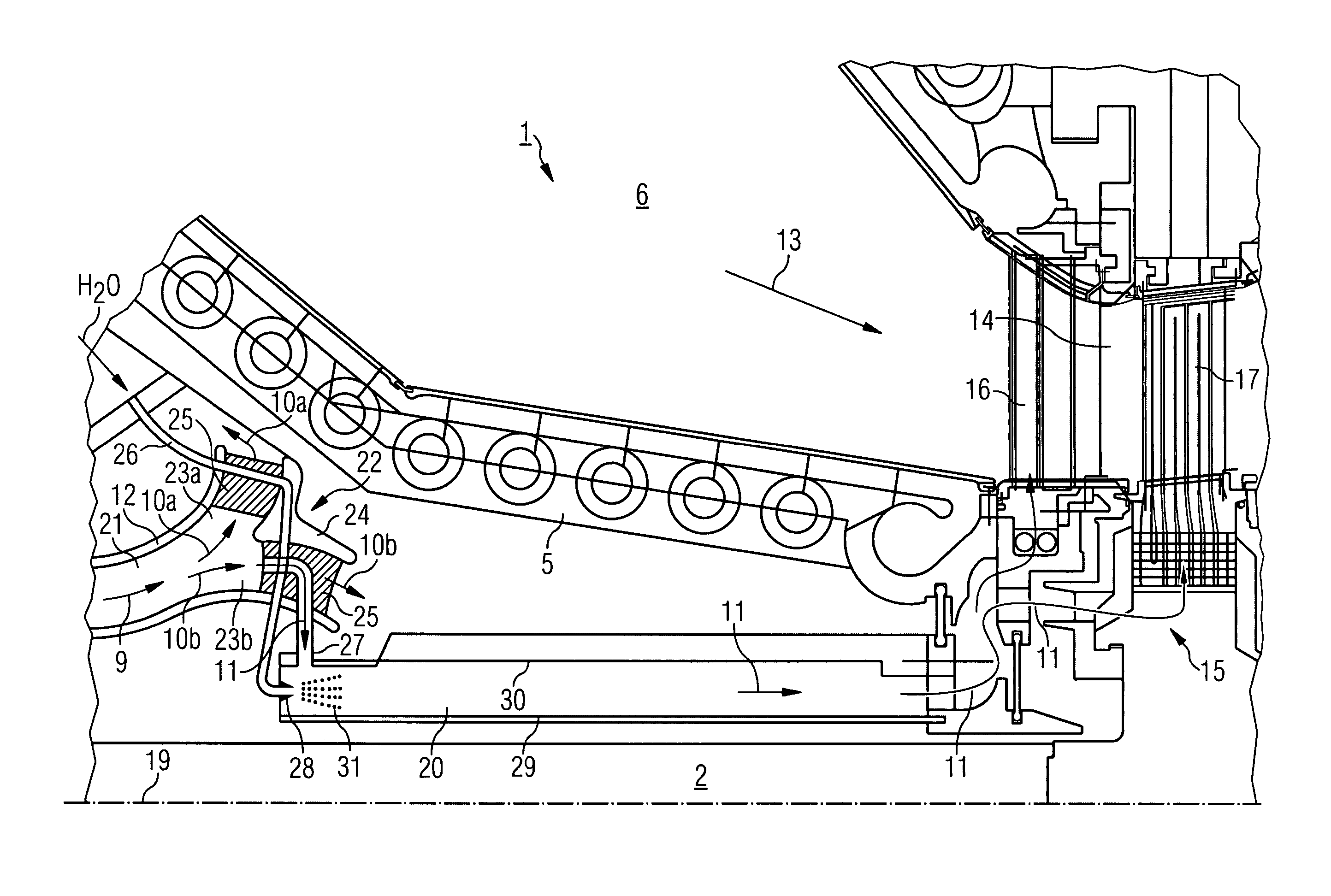
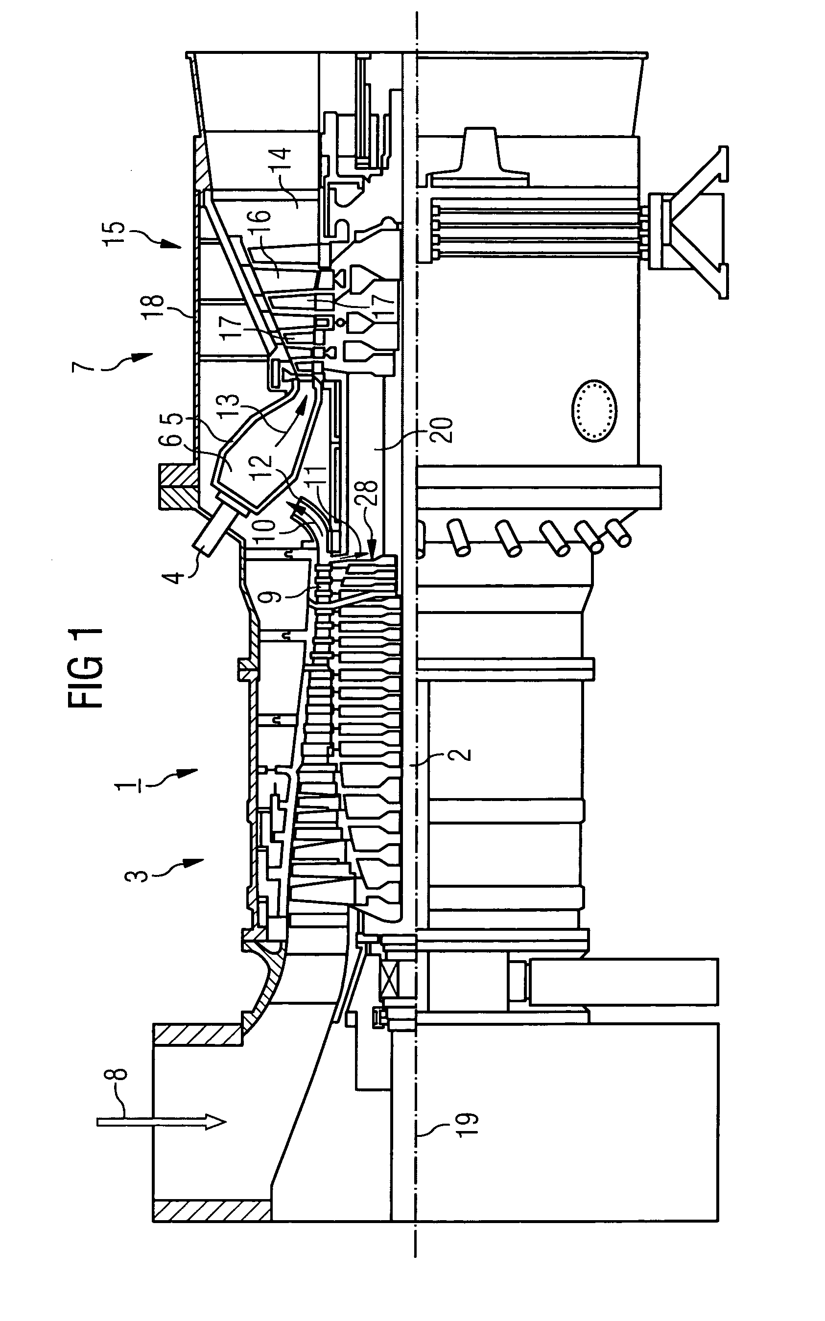
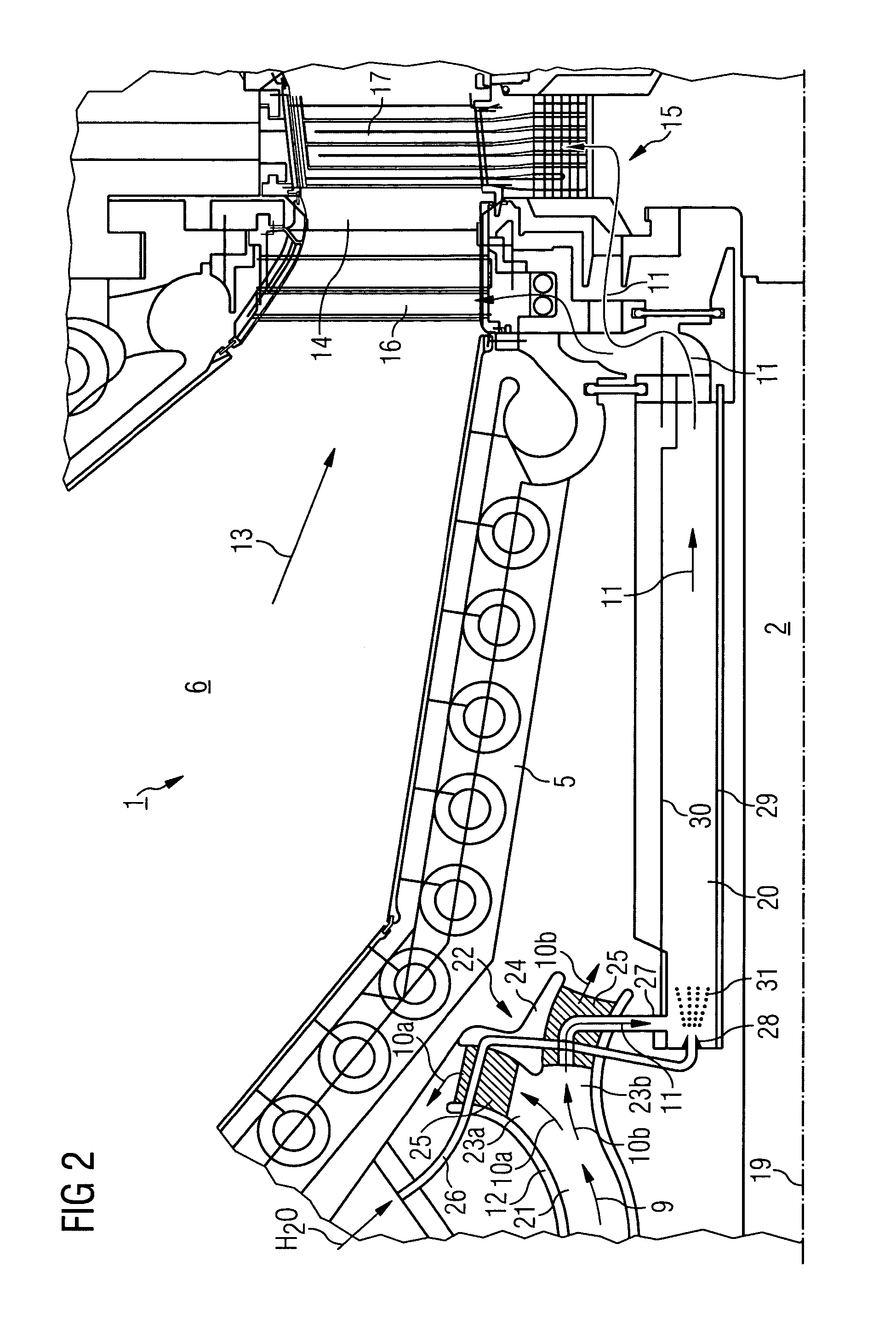
[0025]FIG. 1 shows a longitudinal part section through a turbine 1 formed as a stationary gas turbine, said turbine 1 having a rotor 2, a compressor 3, a burner 4, an annular combustion chamber 5 with a combustion area 6 and a turbine section 7.

[0026]During operation of the turbine 1 one end of the compressor 3 draws in air 8, which is then provided as compressed air 9 at the other end. This is then split into an air mass flow 10 and a cooling air flow 11. The cooling air flow 11 is used to cool the turbine section 7 and the rotor 3, whereas the air mass flow 10 is used first to cool the annular combustion chamber 5 and then for combustion. To this end the air mass flow 10 is diverted by a diffuser 12 in the direction of the annular combustion chamber 5 after leaving the compressor 3 and from there is routed on to the burner 4. Subsequently in the burner 4 the air mass flow 10 is mixed with a combustion agent, which is then combusted in the combustion area 6 of the annular combustio...


PUM


Abstract

The invention relates to a turbine 1, in particular a gas turbine, which along a swivel-mounted rotationally symmetrical rotor 2 has a compressor 3, a combustion chamber 5 and a turbine section 7 formed of a plurality of turbine stages 15, in which each turbine stage 15 contains mutually interacting blades 17 and vanes 16 which a hot working fluid 13 can flow around, with a coolant provided by the compressor 3 for cooling the blades 16, 17, which can flow in a channel along the rotor 2 from the compressor 3 to the turbine section 7 and into which a liquid can be introduced for cooling. In order to specify a turbine in which less wear occurs and in which the lifetime of the components is increased, it is proposed that the channel extends outside the rotor 2 and that the liquid can be introduced at the end of the channel which faces the compressor 2.

Description

CROSS REFERENCE TO RELATED APPLICATIONS[0001]This application claims priority to the European application No. 02025194.8 EP, filed Nov. 11, 2002 under the European Patent Convention and which is incorporated by reference herein in its entirety.FIELD OF THE INVENTION[0002]The invention relates to a turbine according to the preamble of Claim 1.BACKGROUND OF INVENTION[0003]DE 28 52 057 discloses a cooled gas turbine, in which the cooling air extracted from the compressor is cooled by means of water injection. To this end the gas turbine has a water pipe which terminates in a water spray chamber. The water spray chamber is radially limited by the rotor on one side and by a fixed wall embracing the rotor on the other side. The water sprayed in atomizes in the water spray chamber into small water droplets, which evaporate there only partially. The rotor is cooled in this way. The cooled cooling air is then routed further to the blades of the front turbine stages. The water droplets remain...

Claims


Application Information

Patent Timeline
IPC IPC(8): F02C6/04F02C3/04F03D11/00F02C7/16F01D5/08F02C7/18F23R3/04
CPCF01D5/084F01D5/085F02C7/185F05D2260/212F05D2260/232
Inventor TIEMANN, PETER
Owner SIEMENS AG
Why Eureka
Try Eureka