
Low profile self-ligating bracket assembly and method of use

a self-ligating bracket and low profile technology, applied in the field of low-profile self-ligating bracket assembly and method of use, can solve the problems of significant patient discomfort, inability to impart tortional correction forces against the flat slot wall and floor, and damage to the periodontal membrane surrounding the root of the tooth

Inactive Publication Date: 2008-02-26
LANCER ORTHODONTICS
View PDF1 Cites 51 Cited by
  • Summary
  • Abstract
  • Description
  • Claims
  • Application Information

AI Technical Summary

Benefits of technology

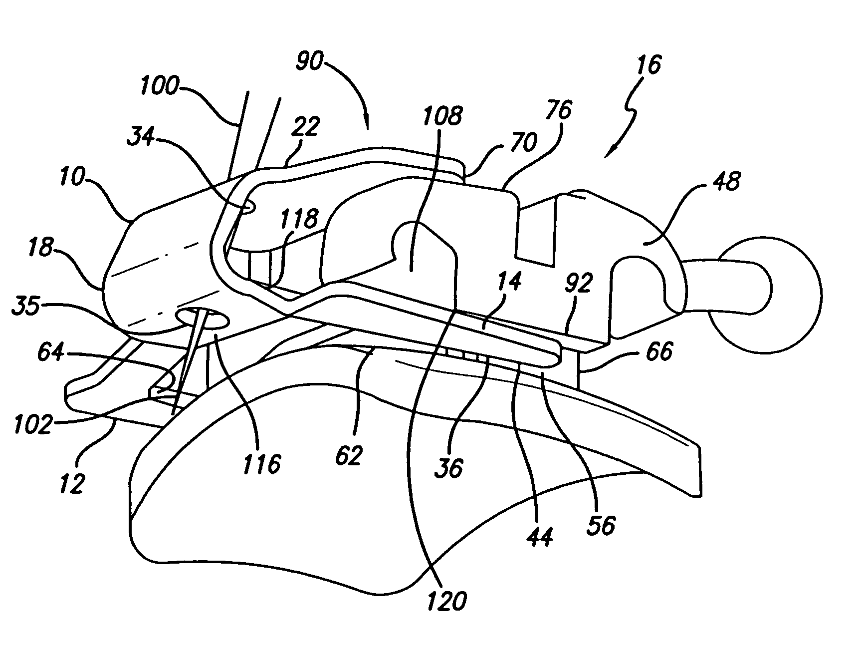
[0043]The metal clip is configured to hold the orthodontic archwire into the bracket archslot. The formed and heat treated clip is produced separately from the bracket and once installed onto the bracket body, it is held in place by inwardly biased paws on arms of the clip that slide in paw / arm-accommodating channels in the bracket base. The clip travels within a range of motion defined by a locked closed position and a locked open position, the range of travel being determined by the geometry of the face and stem of the bracket. A pair of locking ridges protrude from the mesial and distal gingival tie wings to secure the clip in a locked position. A pair of clip travel stops on the mesial and distal incisal tie wings hold the clip in a locked open position. The “locking” action that occurs at each end of this range of motion is also created by the inwardly biased resilient spring properties of the clip being loaded or unloaded in a mesial-distal axis unlike conventional self-ligating detent structures required for a snapping-closed and snapping open in a labial-lingual axis. Such features, if oriented in a labial-lingual axis can impact patient comfort by raising the prominence of the bracket, which the present invention avoids. These travel limiting features allow for the clip to not travel past the point of failure or beyond the body of the bracket tie wings which can make it easier for the clinician to manipulate during treatment.
[0046]In another embodiment, the labial surface of the bracket, in the area of the archslot, is slightly higher in the labial-lingual direction than is the labial surface of the clip. In this embodiment, the clip has protrusions that correspond to recesses in the archslot to lock the clip in the closed position over the archslot. In another embodiment, the clip is locked into a closed position and held there by a pair of locking ridges on the labial surface of the tie wings. This prevents the clip from prematurely opening, yet allows the orthodontist to slide the clip over the locking ridges to move the clip to an open position without passing a point of slipping off the bracket body.

Problems solved by technology

Round archwires used early in treatment are not considered as being true Edgewise wires because being round in cross-section, they are incapable of imparting tortional correction forces against the flat slot walls and floor.
In orthodontics, this type of force acting on the roots of the teeth is called “torque.” To clarify this point, it must be understood that had such wires been used at the beginning of treatment, significant patient discomfort would have resulted, along with insult to the periodontal membrane surrounding the root of the tooth.
Such wires are incapable of spanning the large deflections encountered earlier in treatment without exceeding the effective physiological force range for tooth movement.
To clarify this point, it must be understood that had such wires been used at the beginning of treatment, significant patient discomfort would have resulted, along with insult to the periodontal membrane surrounding the roots of the teeth anchored in the alveolar supporting bone.
Further, such an archwire used inappropriately early in treatment would be likely to take a set and matallurgically yielding.
As described above, round wires are not capable of imparting torqueing forces to a tooth because they lack features needed to engage the Edgewise configuration of the archslot and therefore, they can only tip teeth around an unseen center of resistance in the supporting bone.
Since such a large portion of an orthodontic patient's time in the orthodontist's chair is consumed by changing archwires in this manner, and since such routine archwire changes constitute a major cost to the orthodontic practice and contribute to the cost of treatment for the patient, much inventive effort has gone into identifying innovative chairside systems that reduce the time and cost associated with archwire changing.
The use of elastomeric O-rings however introduce new difficulties and concerns.
For example, they can discolor and stain and they can lose their tractive force capabilities as they absorb water in the mouth.
In either case, any instruments for ligature placement must be sterilized after each use, thus requiring specific in-practice procedures which involve measurable cost.
In reviewing the general field of self-ligating brackets, both proposed and commercialized, it can be said that all versions that employ a vertically-sliding clip inherently compromise patient comfort.
Patient comfort is compromised through the use of such brackets due to the fact that overall bracket prominence must be increased in order to accommodate the increased labial-lingual or buccal-lingual thickness of the bracket driven by the addition of a vertical slot.
In some cases these problems become so severe that orthodontic treatment must be curtailed all together.
As orthodontic patients, they unfortunately pay little attention to instructions from their attending orthodontist to avoid putting certain types of things in the mouth (popcorn, frozen candy bars, crunching ice, etc.).
The structural demands placed on orthodontic brackets and orthodontic armamentarium can be severe.
It is on this area that destructive forces are concentrated and it is at this point that a bracket may structurally yield to those forces.
If brackets could be designed with higher prominence, they could much more easily withstand destructive forces but their higher prominence would result in unacceptable levels of patient discomfort.
So, any bracket system's design is driven by those particular brackets within its prescription that are most vulnerable to distortion and structural failure.
Such advances, however, can ultimately prove useless if self-ligation features drive the height of a bracket system to an unacceptable level where a patient cannot tolerate them.
Even though many prior art self-ligating bracket features may desirably reduce friction and mechanical binding, they nonetheless require a deviation away from the useful twin or Siamese-type bracket design that incorporates two sets of tie-wings.
Such prior art self-ligating designs are limited and incapable of delivering certain corrective forces to the teeth.
These alterations can compromise the benefits of utilizing a twin orthodontic bracket.
Some of the current self-ligation brackets have designs that are not easy to use during the course of orthodontic treatment.
They can be harder to space to disengage the orthodontic wire during treatment or to allow for the next sequential archwire to be space-engaged in its place.
High angles of archwire deflection as an archwire enters and exits the archslot of such a bracket cannot be accommodated.
Highly deflected archwires, such as those typically used early in treatment can circumvent such self-ligation features thereby causing special problems for the orthodontist and greatly compromising the otherwise positive advantages of self-ligation.
Some of the current self-ligation brackets do not allow for the ligation cover to be removed during orthodontic treatment.
Additionally, if the ligation cover comes off the bracket body for some reason during treatment, the ligation cover can not easily be put back in its place to continue the course of treatment without having to remove the entire bracket from the tooth and replace it with a new bracket.
Prior art bracket assemblies can also have clips that undesirably pop open or can be difficult to open or close.
One difficulty of prior art self-ligating brackets is that they tend to become encrusted with calculus, plaque and oral bacteria.
Such a configuration makes it impossible to get a toothbush in place to reach such small internal features.
It is known that all too often, the clips of prior art self-ligating brackets become bound up and locked in place due to buildup of hard plaque deposits.

Method used


Image

  • Low profile self-ligating bracket assembly and method of use
  • Low profile self-ligating bracket assembly and method of use
  • Low profile self-ligating bracket assembly and method of use

Examples


Embodiment Construction

[0089]The new bracket and ligation method provides for a traditional twin or Siamese-type bracket with two distinct pairs of ligation wings to be manufactured by injection molding, sintering, machining or casting. This bracket body incorporates the popular Siamese-type bracket configuration for enhanced rotation-correction capabilities and can be utilized as such by an orthodontist even in the presence of self-ligation features.

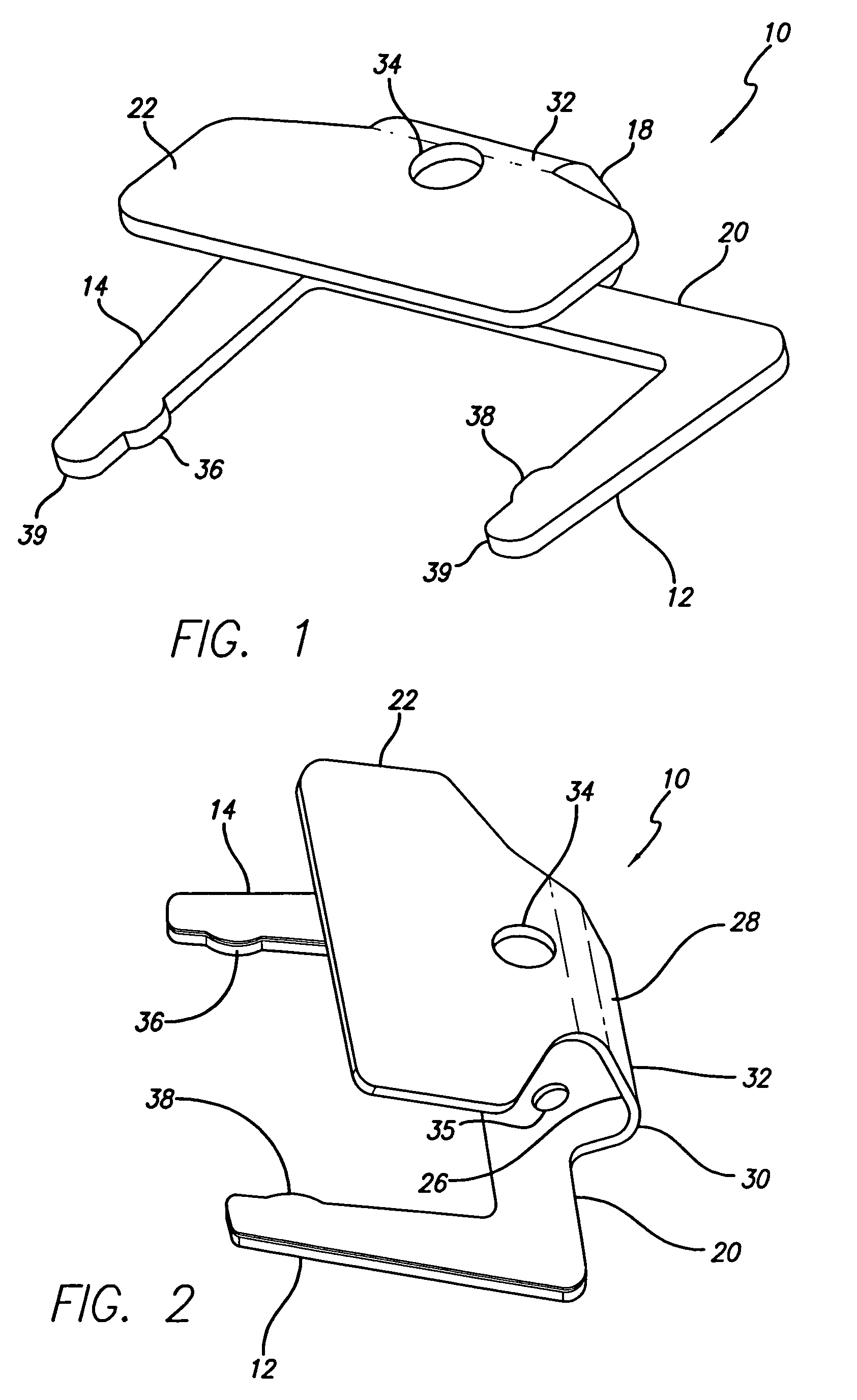
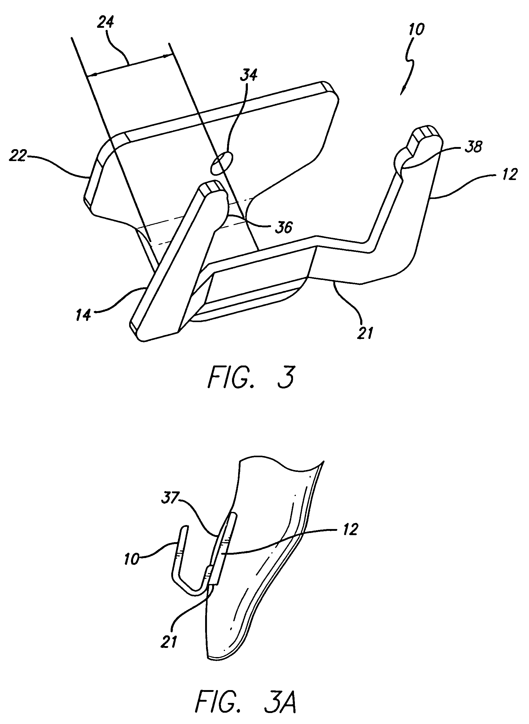
[0090]In keeping with the invention, as shown in FIGS. 1-3, a clip 10 has a U-shaped configuration and includes a pair of arms 12,14 that engage an orthodontic bracket 16 (not shown in FIGS. 1-3). The arms are attached to a clip spine 18 by a cross-bar 20 or preferably, by bilateral crossbar risers 21 (FIG. 3). The clip spine extends generally labially from the crossbar or from a sternum if bilateral crossbar risers are present, and then widens laterally to form a slot cap 22. The overall resiliency of the clip can be controlled by controlling various factors...


PUM


Abstract

A self-ligating orthodontic bracket assembly with selectively removable self-ligation features is configured to provide a low profile to minimize labial-lingual prominence. A clip is configured to snap into the base of the bracket and close over the archwire slot to retain the archwire in the slot. The clip is easily moved to an open position when the archwire is changed out during routine treatment. The clip includes spaced apart arms that, along with the bracket tie-wings, straddle the most outwardly prominent site on the crown of the tooth thereby minimizing labial-lingual profile. The self-ligation capability is achieved without any increase in occlusal-gingival height or measial-distal width of the orthodontic bracket.

Description

CROSS-REFERENCES TO RELATED APPLICATIONS[0001]This application is a continuation-in-part of U.S. Ser. No. 11 / 102,541 filed Apr. 8, 2005, the entire contents of which are incorporated herein by reference.BACKGROUND OF THE INVENTION[0002]The modern orthodontic bracket was developed by Dr. Edward Hartley Angle and became commercially available in the early 1900's. In spite of significant improvements in design, materials and manufacturing processes that have occurred since Dr. Angle's time, the biomechanical functioning of orthodontic brackets remains essentially unchanged.[0003]A variety of orthodontic brackets have been designed over the years generally incorporating varied bonding bases connected to an orthodontic bracket body. The bonding base is connected to the bracket body by brazing or other means or a bracket can be fabricated as an amorphous one-piece unit. The bonding pad provides the interface for a mechanical bond between the bracket and the tooth. Once the brackets are bo...

Claims


Application Information

Patent Timeline
Patent Type & Authority Patents(United States)
IPC IPC(8): A61C3/00
CPCA61C7/287
Inventor CASTNER, DANIEL L.WINER, DAVID
Owner LANCER ORTHODONTICS
Learn More