Method for operating a power tool

a power tool and tool body technology, applied in the direction of emergency protection arrangements for limiting excess voltage/current, safety/protection circuits, field or armature current control, etc., can solve the problems of irreversible damage of energy accumulators and greatly reduced service li

Active Publication Date: 2008-02-26
ROBERT BOSCH GMBH
View PDF13 Cites 1195 Cited by
  • Summary
  • Abstract
  • Description
  • Claims
  • Application Information

AI Technical Summary

Benefits of technology

[0006]The energy accumulator is successfully protected, and good regulating properties for the power tool are attained. A clock frequency is generated by an electronic unit, with which a gate of a MOSFET, which supplies operating voltage to the drive motor, is switched on with each cycle, it being possible to switch off the MOSFET within one cycle using different signals, as a function of operating parameters. When the MOSFET is switched off, the first result is not that the drive motor is shut off, but rather that a pulse width of the drive motor is reduced. The motor current and, therefore, the torque remain high or even at a maximum level, and only the rotational speed decreases.
[0007]Preferably, when a specified threshold value of an operating parameter of the power tool is reached, a pulse width of triggering signals of the drive motor is reduced. The power tool merely reduces the pulse width, but does not shut off completely.
[0008]In a favorable embodiment, when a maximum permissible threshold of an electric current from the energy accumulator is reached, the pulse width is reduced.
[0010]In a favorable embodiment, when a maximum permissible temperature of the energy accumulator is reached, a measured current signal is modified such that the drive motor is gently turned off. By intentionally and specifically adulterating the current signals, an uncomfortable, abrupt shut-off can be prevented.
[0012]In a favorable embodiment, drilling-site illumination of the power tool is not switched off until the drive motor is shut off completely. The power tool operator can continue working nearly interference-free even when threshold values are exceeded or fallen below, while the energy accumulator is reliably protected against harmful total discharge.

Problems solved by technology

When rechargeable energy accumulators are used with power tools, total discharge of the energy accumulator must be avoided, since this can cause the energy accumulator to become irreversibly damaged, or, at the least, its service life can be greatly reduced.

Method used


Image

  • Method for operating a power tool
  • Method for operating a power tool
  • Method for operating a power tool

Examples


Embodiment Construction

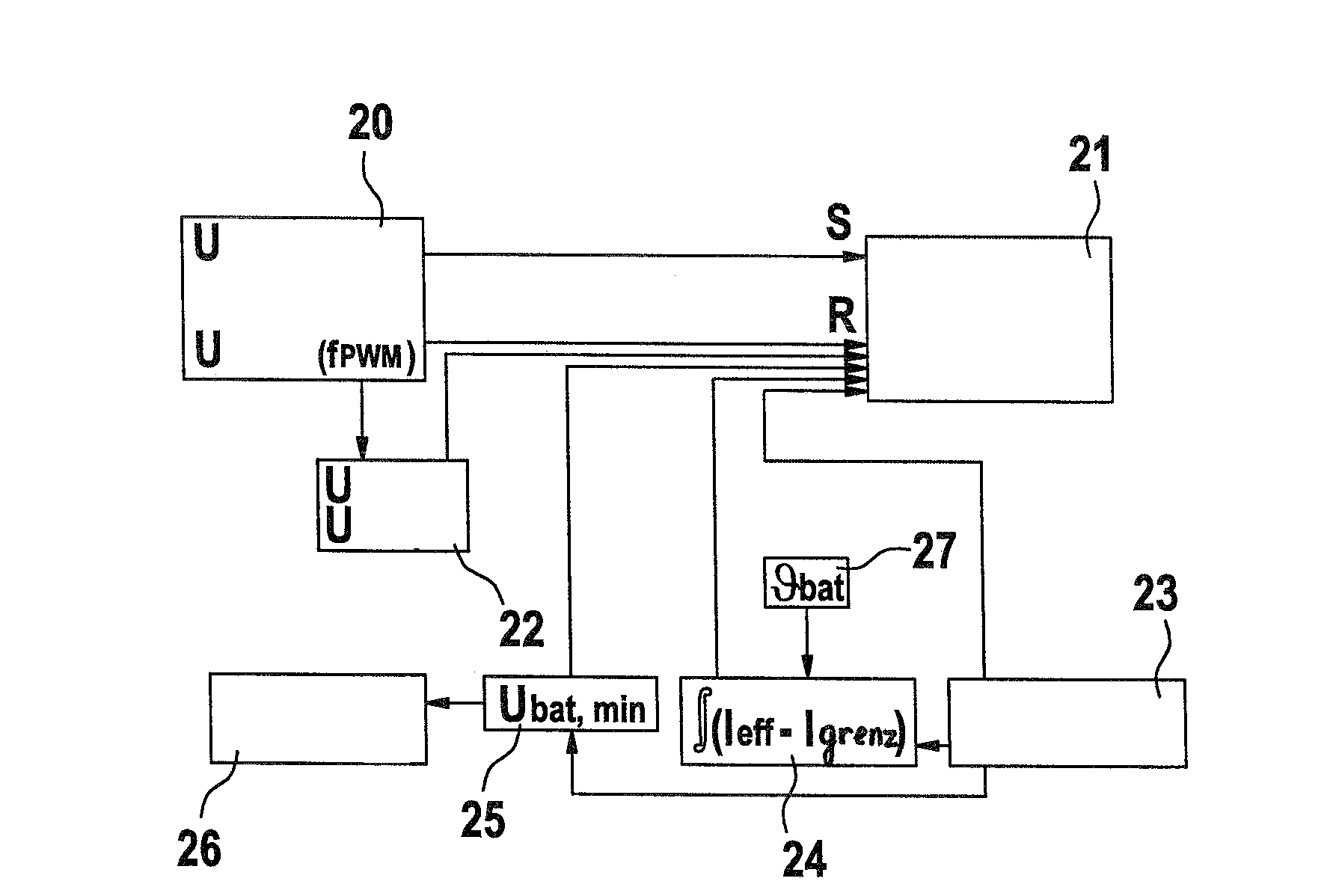
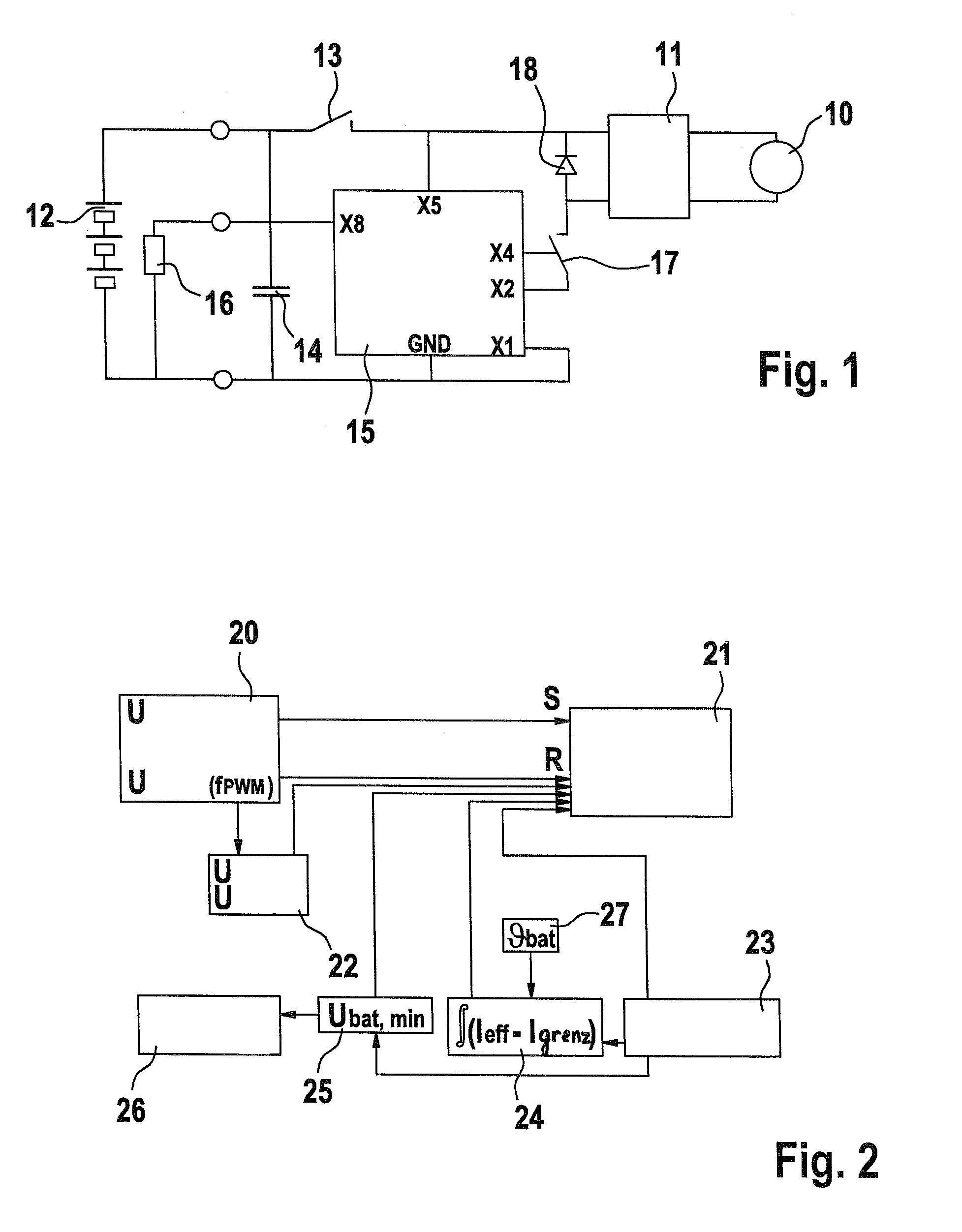
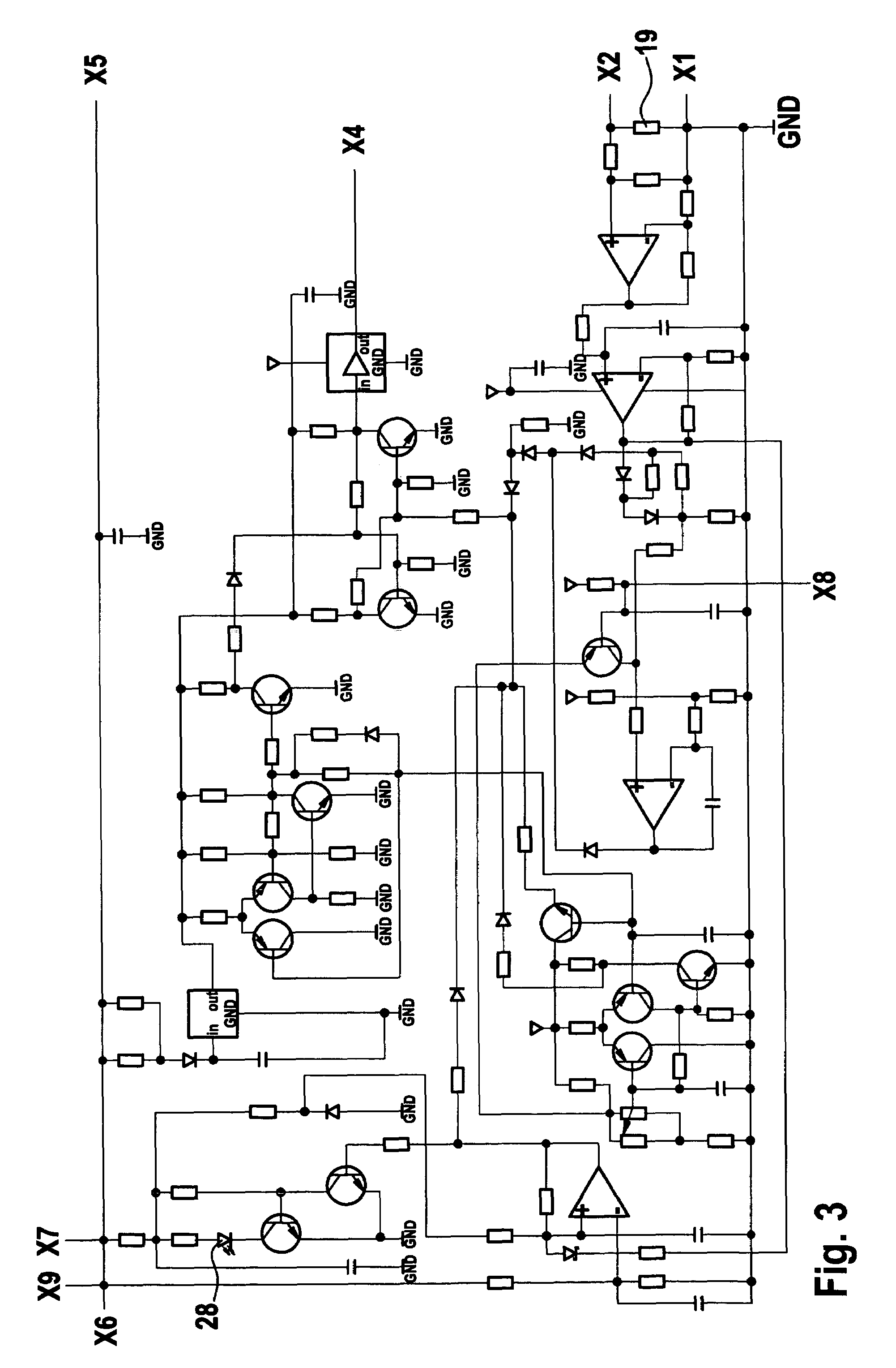
[0018]FIG. 1 shows a schematic diagram of a preferred power tool. An electronic unit 15 controls gate impulses of a MOSFET 17 acting as a switch, which supplies operating voltage from an energy accumulator 12 to a switch 11 and, therefore, a drive motor 10. FIG. 3 shows, as an example, an overall schematic diagram of electronic unit 15. The interplay of individual functional blocks of the method according to the present invention is depicted in FIG. 2.

[0019]Switch 11 switches the direction of rotation of drive motor 10 between right and left rotation as desired. In a free-wheeling phase, the motor current flows through a free-wheeling diode 18. Gate X4 of MOSFET 17 can be applied to switch 11. A measuring resistor 19 is connected between source X2 of MOSFET 17 and negative terminal X1 of energy accumulator 12, as shown in FIG. 3, with which an electrical current flow from energy accumulator 12 is measured.

[0020]A temperature of energy accumulator 12 is determined using a sensor 16 a...


PUM


Abstract

In a method for operating a power tool with an energy accumulator, in particular a rechargeable energy accumulator, which supplies power to an electric drive motor, a clock frequency is generated by an electronic unit, with which a gate of a MOSFET—which supplies operating voltage to the drive motor—is switched on with each cycle, and a switching-off of the MOSFET is carried out within one cycle using different signals, as a function of operating parameters.

Description

CROSS-REFERENCE TO A RELATED APPLIACTION[0001]The invention described and claimed hereinbelow is also described in German Patent Application DE 102005020377.9 filed on May 2, 2005. This German Patent Application, whose subject matter is incorporated here by reference, provides the basis for a claim of priority of invention under 35 U.S.C. 119(a)-(d).BACKGROUND OF THE INVENTION[0002]The present invention is directed to a method for operating a power tool.[0003]When rechargeable energy accumulators are used with power tools, total discharge of the energy accumulator must be avoided, since this can cause the energy accumulator to become irreversibly damaged, or, at the least, its service life can be greatly reduced.SUMMARY OF THE INVENTION[0004]Accordingly, it is an object of the present invention to provide a method for operating a power tool, which is a further improvement of the existing methods.[0005]The method according to the present invention for operating a power tool with an e...

Claims


Application Information

Patent Timeline
Patent Type & Authority Patents(United States)
IPC IPC(8): B23Q5/00H02H7/08
CPCH02H7/0833H02J7/0031H02J2007/004H02J7/00306H02J7/00309H02H7/18H02P7/29
Inventor LOHR, GUENTER
Owner ROBERT BOSCH GMBH
Why Eureka
Try Eureka