Equipment for subsurface autofluorescence spectroscopy

Inactive Publication Date: 2008-02-26
MAUNA KEA TECHNOLOGIES
View PDF3 Cites 9 Cited by
  • Summary
  • Abstract
  • Description
  • Claims
  • Application Information

AI Technical Summary

Benefits of technology

[0011]The present invention is thus based on certain of the means mentioned above for producing a confocal image, namely carrying on the same fibres or fibres the excitation signal and the emitted return signal, and the use of an optical head focussing the excitation signal into a point at a depth. The focussing combined with the confocal character (obtained thanks to the return of the autofluorescence signal by the same optical fibre or fibres), makes it possible to obtain a high spatial resolution. The advantage compa

Problems solved by technology

This leads to a poor resolution, with a mixture of infor

Method used


Image

  • Equipment for subsurface autofluorescence spectroscopy
  • Equipment for subsurface autofluorescence spectroscopy
  • Equipment for subsurface autofluorescence spectroscopy

Examples


Example

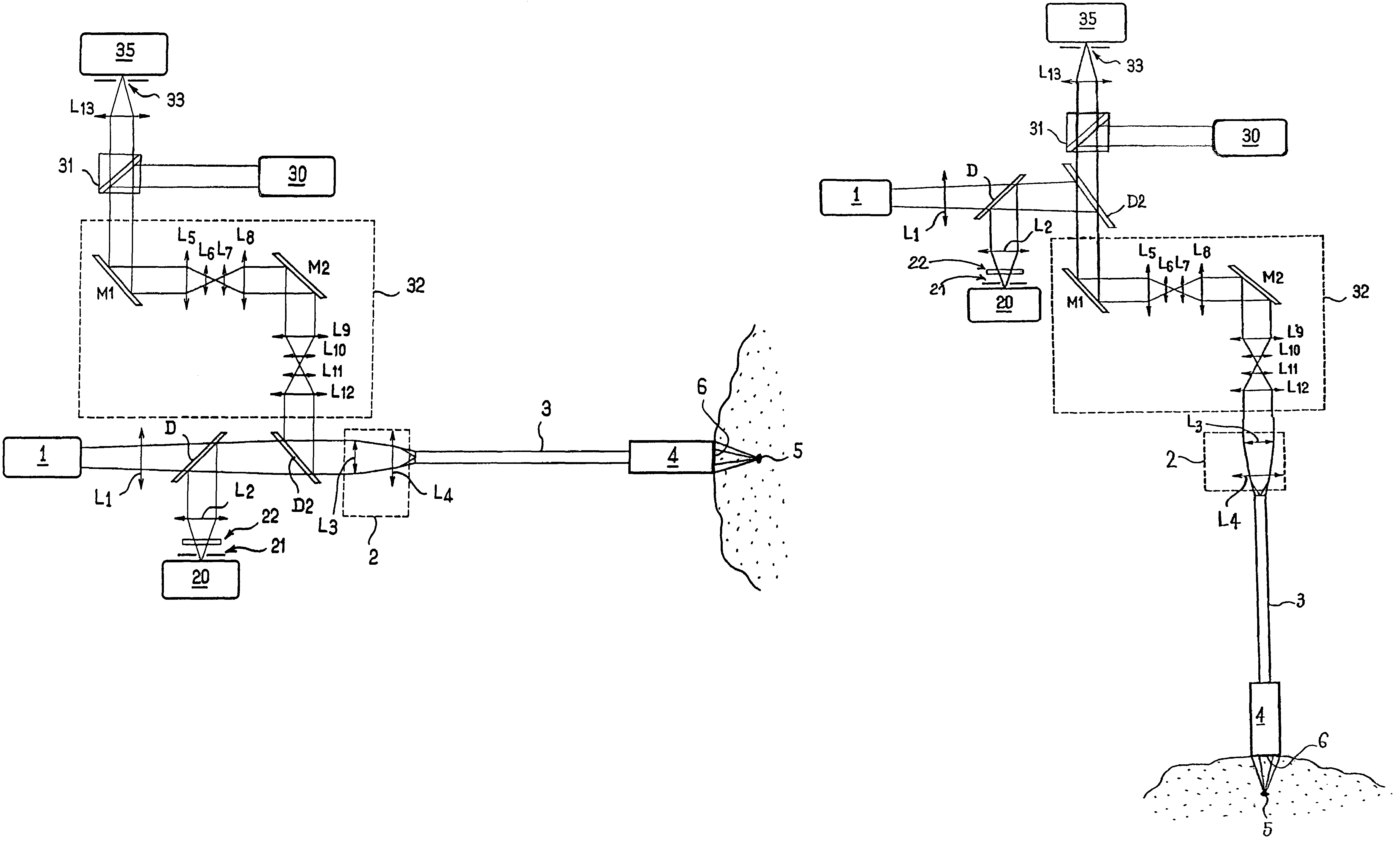
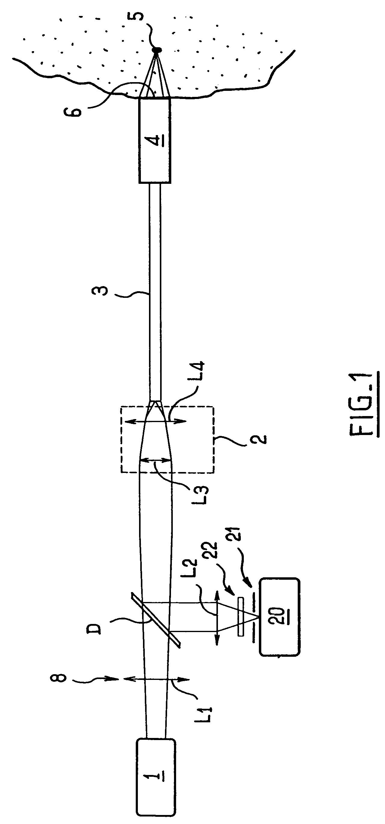
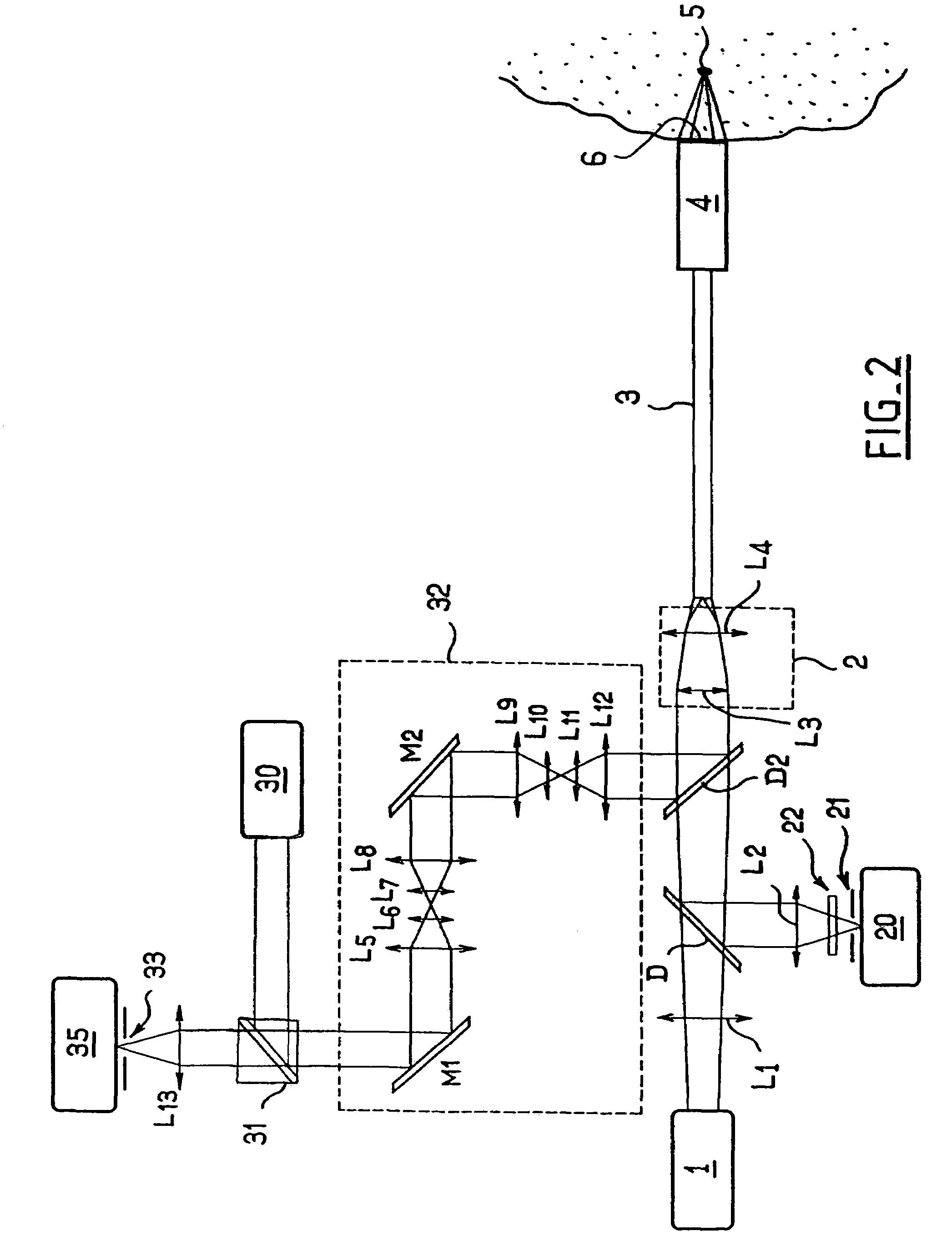
[0032]According to the embodiment chosen and represented in FIG. 1, an equipment is proposed for producing a subsurface spectroscopic analysis at a given depth, comprising a source 1 producing an excitation signal, a means for injecting 2 said signal into an organized optical fibre bundle 3 at the end of which is arranged an optical head 4 adapted for modifying the excitation signal leaving said optical fibre bundle 3 in order to create a convergent beam focussed on a zone 5 underlying the zone of contact 6 with the optical head 4.

[0033]The source 1 used is chosen in order to allow excitation of the endogenous fluorophores present in the biological tissues of the observed site, in particular in a wavelength range of 300-500 nm. Typically a 405+ / −10 nm diode laser can be used. Other sources such as solid lasers or gas lasers with or without harmonic generators can also be suitable with other wavelengths in order to excite other endogenous fluorophores.

[0034]The equipment comprises a ...


PUM


Abstract

An equipment includes an excitation source (1), elements for injecting (2) an excitation signal produced by the source in an ordered bundle (3) of flexible optical fibers, elements for analyzing (21, 22) an emitted autofluorescence signal. The equipment also includes at the output of the optical fiber bundle (3) an optical head (4) designed to be placed in contact with the biological tissue (6), the optical head being equipped with optical elements adapted to cause the excitation signal output from the bundle (3) to converge into a subsurface analyzing zone (5), the same optical fiber(s) used for excitation of the bundle (3) being used for detecting the signal emitted by the subsurface analyzing zone, elements (D) placed upstream of the injection elements (2) being further provided to separate the wavelength of the excitation signal and the wavelength of the autofluorescence signal.

Description

BACKGROUND OF THE INVENTION[0001]The present invention relates to an equipment for subsurface autofluorescence spectroscopy. More particularly, the equipment according to the invention is of the type using an excitation signal carried by one or more flexible optical fibres.DESCRIPTION OF THE RELATED ART[0002]The fields of application of the invention are in-vivo spectroscopic biological tissue analysis, on humans or animals, external or internal and accessible using the instrument channel of an endoscope into which the optical fibres can be introduced, and also the ex-vivo analysis of tissue samples from biopsies, and the in-vitro analysis of cultures in cell biology.[0003]At present the medical fields of gastroenterology, respirology, gynaecology, urology, otorhinolaryngology, dermatology, ophthalmology, cardiology and neurology are concerned.[0004]Biological tissues contain endogenous fluorophores capable, in response to a luminous excitation of appropriate wavelength, of emitting...

Claims


Application Information

Patent Timeline
IPC IPC(8): A61B6/00A61B1/00A61B5/00G01N21/64
CPCA61B5/0071A61B5/0075A61B5/0084G01N21/6456G01N21/6486A61B5/0068
Inventor GENET, MAGALIEBOURG-HECKLY, GENEVIEVEVILETTE, SANDRINELACOMBE, FRANCOISLOISEAU, ALEXANDREABRAT, BENJAMIN
Owner MAUNA KEA TECHNOLOGIES
Why Eureka
Try Eureka