Surgically implantable knee prosthesis

a knee joint and prosthesis technology, applied in knee joints, ligaments, medical science, etc., can solve the problems of chondromalacia, damage to these surfaces, degenerative tearing of meniscal cartilage,

Inactive Publication Date: 2008-03-04
FELL BARRY M +1
View PDF92 Cites 66 Cited by
  • Summary
  • Abstract
  • Description
  • Claims
  • Application Information

AI Technical Summary

Benefits of technology

[0021]Still further, a prosthesis is provided for implantation into a knee joint compartment between a femoral condyle and its corresponding tibial plateau. The prosthesis includes a body free of any means of fixation within the knee joint compartment, the body having a generally elliptical shape in plan and having a top surface and an opposed, substantially flat bottom surface. The body comprises a material capable of spanning any defects in the femoral condyle and tibial plateau without substantially deforming into the defects.

Problems solved by technology

Damage to these surfaces is generally due to genetic predisposition, trauma, and / or aging.
The result is usually the development of chondromalacia, thinning and softening of the articular cartilage, and degenerative tearing of the meniscal cartilage.
In patients with osteoarthritis, the degenerative process typically leads to an asymmetric wear pattern that leaves one compartment with significantly less articular cartilage covering the weight bearing areas of the tibia and femur than the other compartment.
As the disease progresses, large amounts of articular cartilage are worn away.
The disease manifests itself as periodic to continuous pain that can be quite uncomfortable for the patient.
This increasing joint laxity is suspected of causing some of the pain one feels.
All of this shifting of the knee component geometry causes a misalignment of the mechanical axis of the joint.
This misalignment causes an increase in the rate of degenerative change to the diseased joint surfaces, causing an ever-increasing amount of cartilage debris to build up in the joint, and further causing joint inflammation and subsequent pain.
Currently, there is a void in options used to treat the relatively young patient with moderate to severe chondromalacia involving mainly one compartment of the knee.
Some patients cannot tolerate or do not want the risk of potential side effects of NSAIDS.
Repeated cortisone injections actually weaken articular cartilage after a long period of time.
HA has shown promising results, but is only a short term solution for pain.
Arthroscopic debridement alone frequently does not provide long lasting relief of symptoms.
Unfortunately, the lack of long term success of these treatments leads to more invasive treatment methods.
These procedures are not suitable for addressing large areas of degeneration.
In addition, osteochondral allografts can only be used to address defects on the femoral condyle, as tibial degeneration cannot be addressed with this technique.
However, an HTO does leave a hard sclerotic region of bone which is difficult to penetrate, making conversion to a total knee replacement technically challenging.
Unfortunately, these procedures resect significant amounts of bone (typically 7-9 mm), and primary (first arthroplasty performed on the joint) procedures have a functional life span of only 5-10 years, such that younger patients will likely require revision surgery as they age.
Furthermore, the amount of bone loss that is inherent in a UKR or TKR makes a revision (secondary) procedure much more difficult in the future as even more bone must be removed.
Revision knee replacement surgery is usually extensive and results in predictably diminished mechanical life expectancy.
Unfortunately, these natural articular materials and surgical technology required to accomplish this replacement task do not yet exist.
Attaching a new bearing surface to the femoral condyle is technically challenging and was first attempted, with limited success, over 40 years ago with the MGH (Massachusetts General Hospital) knee.
Tibial covering devices such as the McKeever, Macintosh, and Townley tibial tray maintained the existing femoral surface as the bearing surface but, like the MGH knee, all required significant bone resection, thus making them less than ideal solutions as well.
These devices also made no particular attempt to match the patient's specific femoral or tibial geometry, thus reducing their chances for optimal success.
Because these devices were made of CoCr, which has different viscoelastic and wear properties from the natural articular materials, any surface geometry which did not closely match the bearing surface of the tibia or femur could cause premature wear of the remaining cartilage due to asymmetric loading.
However, these techniques are limited by one's ability to first of all fashion these materials in a conformal manner to replicate the existing knee geometry, while at the same time maintaining their location within the joint, while further being able to survive the mechanical loading conditions of the knee.

Method used


Image

  • Surgically implantable knee prosthesis
  • Surgically implantable knee prosthesis
  • Surgically implantable knee prosthesis

Examples


first embodiment

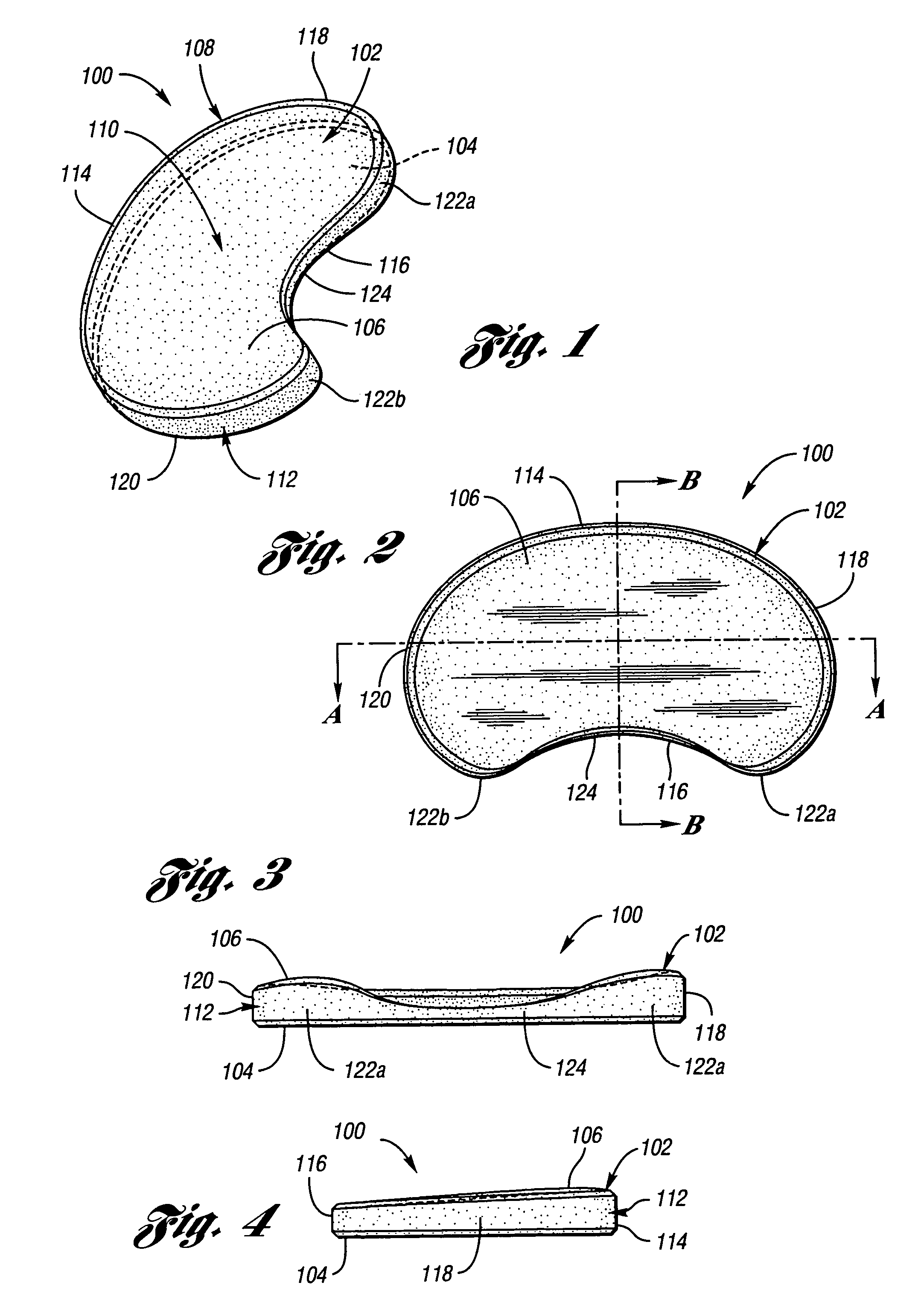
[0043]Turning now to FIGS. 1-4, an implantable knee prosthesis according to the present invention is illustrated and designated generally by reference numeral 100. Prosthesis 100 includes a body 102 having a generally elliptical shape in plan and including a bottom, or tibial, surface 104 and an opposite top, or femoral, surface 106. Bottom surface 104 is substantially flat, wherein the contour of bottom surface 104 is preferably generally the same as the associated contour of the tibial plateau after any necessary bone resection as described below. Due to its flat contour, bottom surface 104 is advantageously optimized for use with tibial plateaus with large (>0.5 mm) defects. When large tibial defects are present, potential complications can include the femoral condyle disengaging from the femoral surface of the prosthesis, traveling anteriorly or posteriorly independent of the prosthesis, and causing the prosthesis to disclocate or cause pain for the patient. Since flat bottom su...

second embodiment

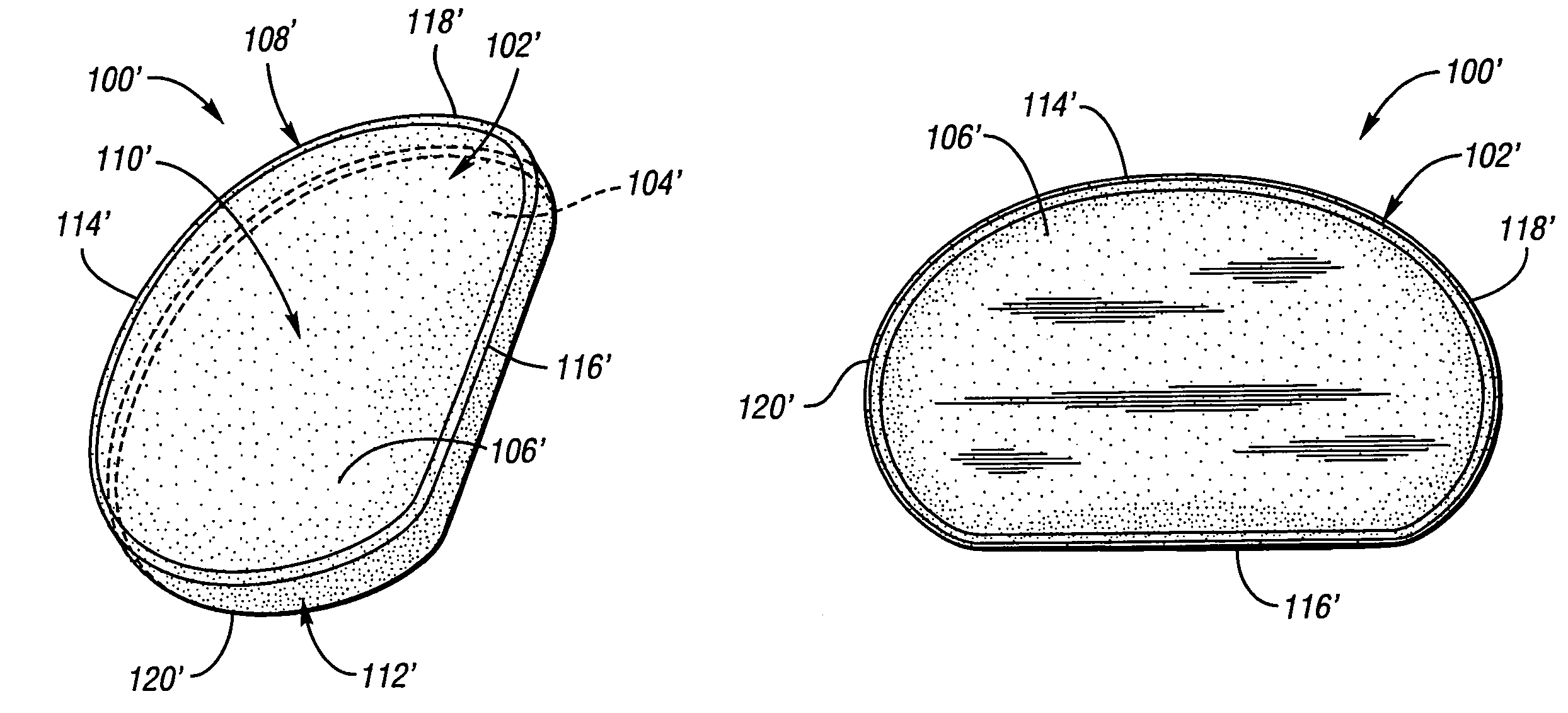
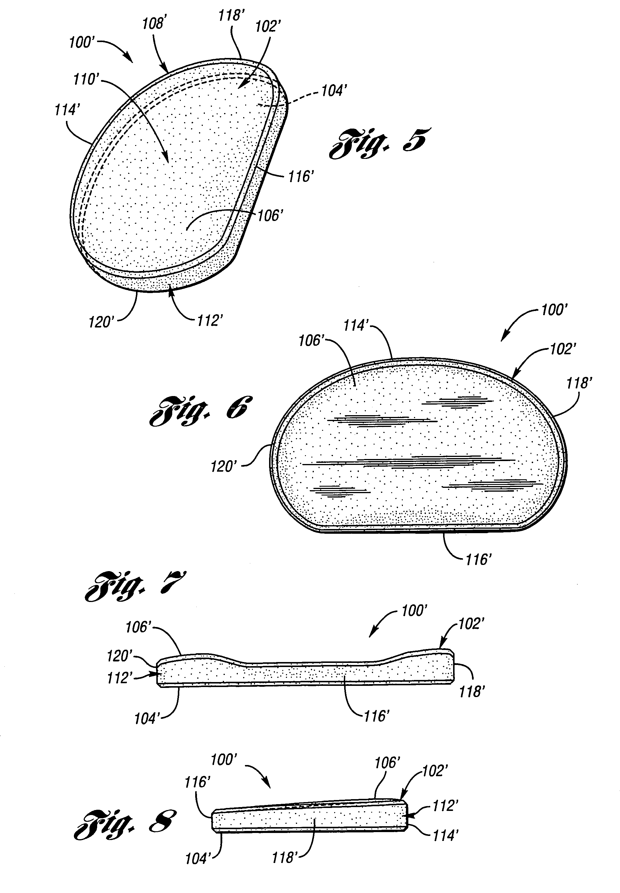
[0047]With reference to FIGS. 5-8, prosthesis 100′ is depicted, wherein reference numerals are the same as the embodiment of FIGS. 1-4 except for the addition of a prime (′) designation. If the tibial spine has been substantially resected, no side indentation is necessary and prosthesis 100′ is preferably used as it has a generally straight second side 116′ without lobes 122a, 122b. With this exception, it is understood that the foregoing description of prosthesis 100 applies equally well to prosthesis 100′. Accordingly, it is understood that the term “generally elliptical” is intended to include all construction methods which yield a generally planar shape which is longer in one direction than in the transverse direction and has rounded corners, and that prosthesis 100, 100′ of the present invention is not otherwise limited to any particular shape.

[0048]Contrary to most devices which are composed of soft, compliant material designed to assume the function of the natural meniscus wh...


PUM


Abstract

A prosthesis is provided for implantation into a knee joint compartment between a femoral condyle and its corresponding tibial plateau which is suitable for patients having large tibial defects. The prosthesis includes a hard body free of fixation within the knee joint compartment. The body has a generally elliptical shape in plan and a pair of opposed surfaces including a substantially flat bottom surface and an opposed top surface.

Description

BACKGROUND OF THE INVENTION[0001]1. Field of the Invention[0002]The present invention pertains to a prosthetic device which is surgically implantable into a body joint, and more particularly to a knee joint prosthesis which may be surgically implanted between the femoral condyle and tibial plateau of the knee compartment.[0003]2. Background Art[0004]Articular cartilage and meniscal cartilage provide the mobile weight bearing surfaces of the knee joint. Damage to these surfaces is generally due to genetic predisposition, trauma, and / or aging. The result is usually the development of chondromalacia, thinning and softening of the articular cartilage, and degenerative tearing of the meniscal cartilage. Various methods of treatment are available to treat these disease processes. Each option usually has specific indications and is accompanied by a list of benefits and deficiencies that may be compared to other options.[0005]The healthy knee joint has a balanced amount of joint cartilage a...

Claims


Application Information

Patent Timeline
Patent Type & Authority Patents(United States)
IPC IPC(8): A61F2/38A61F2/00A61F2/08
CPCA61F2/38A61F2/3872A61F2/3868A61F2002/30133A61F2002/30324A61F2002/3895A61F2230/0015A61F2250/0036
Inventor FELL, BARRY M.HALLOCK, RICHARD H.
Owner FELL BARRY M
Why Eureka
Try Eureka