Vertical color filter sensor group array with full-resolution top layer and lower-resolution lower layer

Inactive Publication Date: 2008-03-04
FOVEON
View PDF40 Cites 24 Cited by
  • Summary
  • Abstract
  • Description
  • Claims
  • Application Information

AI Technical Summary

Benefits of technology

[0027]In a class of embodiments, the inventive array is an N×M array of sensor group cells, where each cell includes “S” VCF sensor groups, and S is a small integer (e.g., S=4). The top sensors of all sensor groups of each cell together constitute a top layer of sensors, and the other sensors of each cell together constitute at least one low layer of sensors below the top layer. Each cell includes S sensors in the top layer and fewer than S sensors in each low layer. In preferred embodiments in this class, each cell includes at least one shared sensor in each low layer. The array is typically implemented a block of solid material including structures formed on a substrate (e.g., by a semiconductor integrated circuit fabrication process). Each cell includes sensor selection switches (e.g., transistors formed on or at a top surface of the array) coupled between the cell's sensors and a single “sense” node. The sensor selection switches are controlled during readout to accomplish sequential readout of each of the cell's sensors at the cell's sense node (e.g., by asserting a sequence of voltages, each indicative of the output of a different one of the sensors, at the sense node). For example, when S=4, each cell can include six sensor selection switche

Problems solved by technology

Such sensors have the disadvantage of occupying a relatively large area per resolution element as these sensors are tiled together in a plane.
In addition, reconstruction of a color image from such a sensor array is computationally intensive and often results in images with artifacts, defects, or inferior resolution.
In contrast, time sequential

Method used


Image

  • Vertical color filter sensor group array with full-resolution top layer and lower-resolution lower layer
  • Vertical color filter sensor group array with full-resolution top layer and lower-resolution lower layer
  • Vertical color filter sensor group array with full-resolution top layer and lower-resolution lower layer

Examples


Embodiment Construction

[0043]Persons of ordinary skill in the art will realize that the following description of the present invention is illustrative only and not in any way limiting. Other embodiments of the invention will readily suggest themselves to such skilled persons having the benefit of this disclosure.

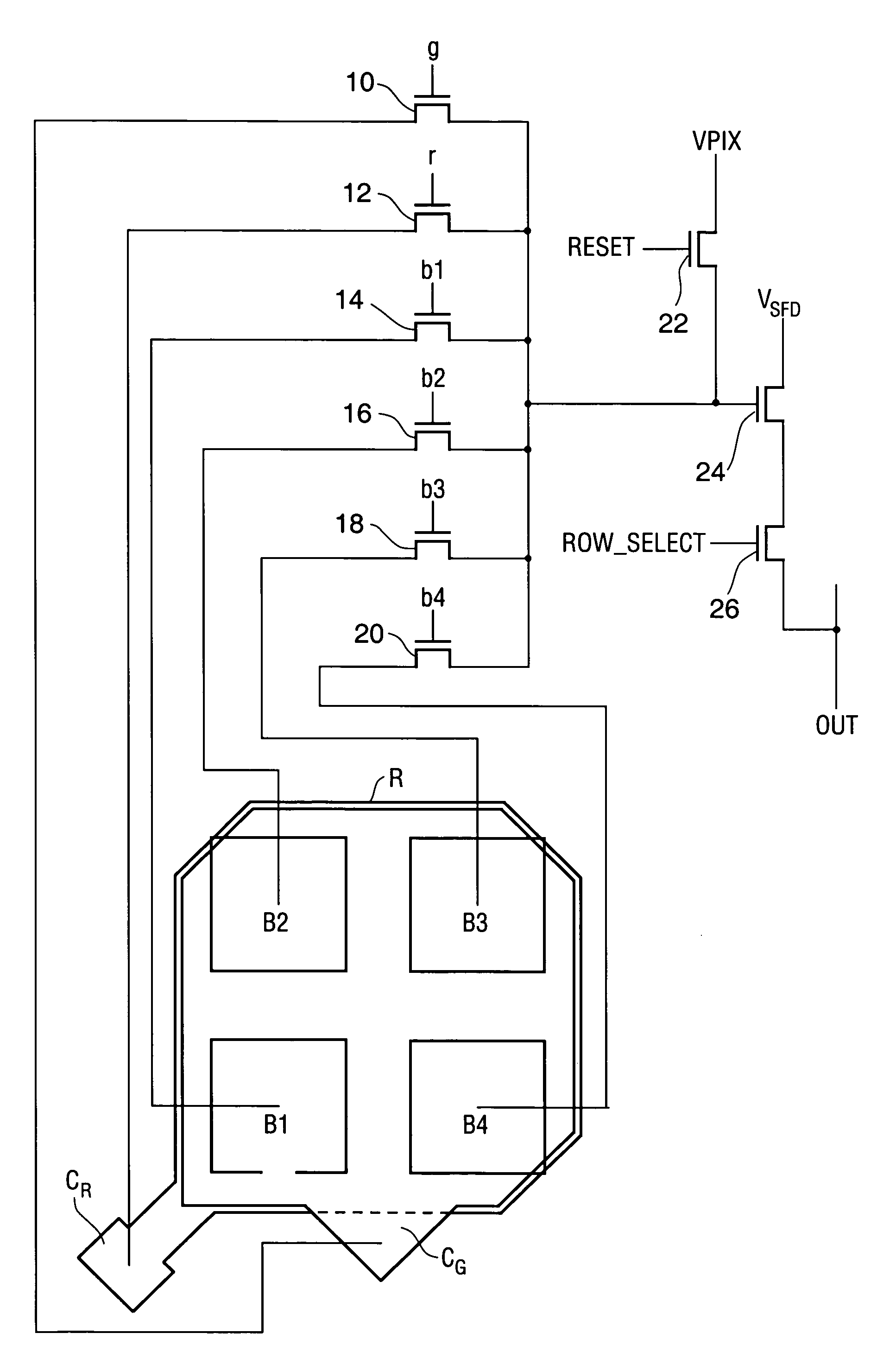
[0044]Each sensor of a VCF sensor group senses photons by directly or indirectly converting their energy into electron-hole pairs. This conversion occurs in semiconducting material. A VCF sensor group is typically implemented so that the output of each sensor in the group is indicative of incident photon intensity in a different wavelength band. The radiation that reaches each sensor in a VCF sensor group has a different wavelength-intensity spectrum due to the filtering action of the material forming the sensor group. Thus, all sensors in a VCF sensor group can be identical and each sensor can still produce an output that is indicative of a different wavelength band. In some embodiments, however,...


PUM


Abstract

An array of vertical color filter (VCF) sensor groups, optionally including or coupled to circuitry for converting photogenerated carriers produced in the sensors to electrical signals, and methods for reading out any embodiment of the array. The array has a top layer (including the top sensors of the sensor group) and at least one low layer including other ones of the sensors. Only the top layer can be read out with full resolution. Each low layer can only be read out with less than full resolution to generate fewer sensor output values than the total number of pixel sensor locations. Typically, the sensor groups are arranged in cells, each cell including a S sensor groups (e.g., S=4), with S sensors in the top layer and fewer than S sensors in each low layer of the cell. Typically, each cell includes at least one shared sensor (a sensor shared by two or more VCF sensor groups) in each low layer, and each cell includes sensor selection switches (e.g., transistors) between the cell's sensors and a sense node.

Description

RELATED APPLICATIONS[0001]This application is a continuation in part of U.S. patent application Ser. No. 10 / 738,484, filed Dec. 17, 2003, and issued as U.S. Pat. No. 6,998,660 on Feb. 14, 2006, and a continuation in part of U.S. patent application Ser. No. 10 / 355,723, filed Jan. 31, 2003, now abandoned entitled VERTICAL COLOR FILTER SENSOR GROUP WITH CARRIER-COLLECTION ELEMENTS OF DIFFERENT SIZE AND METHOD FOR FABRICATING SUCH A SENSOR GROUP.BACKGROUND OF THE INVENTION[0002]1. Field of the Invention[0003]The present invention relates to arrays of photosensitive sensor groups, each sensor group comprising vertically stacked sensors (typically, vertically stacked red, green, and blue sensors), and each sensor group in the array positioned at a different pixel location. In each sensor group, semiconductor material chromatically filters incident electromagnetic radiation vertically (optionally, other material also filters the radiation) and each sensor simultaneously detects a different...

Claims


Application Information

Patent Timeline
IPC IPC(8): H01L31/00
CPCH01L27/14647H01L27/14641H04N9/045H04N25/17
Inventor LYON, RICHARD F.HUBEL, PAUL M.BAGULA, MARK O.MERRILL, RICHARD B.
Owner FOVEON
Why Eureka
Try Eureka