Heat sink module for dissipating heat from a heat source on a motherboard

a heat sink and motherboard technology, applied in the direction of power cables, semiconductor/solid-state device details, cables, etc., can solve the problems of affecting operation efficiency, high temperature accordingly, and a little limitation of the operation temperature of each of the electric elements, so as to reduce manufacturing time, reduce weight, and reduce the effect of high temperature resistan

Active Publication Date: 2008-03-04
INVENTEC CORP
View PDF9 Cites 32 Cited by
  • Summary
  • Abstract
  • Description
  • Claims
  • Application Information

AI Technical Summary

Benefits of technology

[0008]In a heat sink module, the heat sink plate extending to the heat source and covering the fan set is used to conduct the heat from the heat source on the motherboard to the fan set for heat sinking. The heat sink module includes a fan set and a heat sink plate. The fan set is integrated as a whole, reducing manufacturing time, and the material of the fan set is plastic, thus reducing the weight as well. Furthermore, the material of the heat sink plate is of high temperature resistance and preferable heat conductivity; for example aluminum or an aluminum alloy, thus providing a good heat conduction effect. As such, the heat generated from the heat source is taken to the fan set to be dissipated. The fan set is fixed to the heat sink plate by the design of the hook portion of the fan set catching the ear portion of the heat sink plate, so that the heat sink plate can cover and be fixed on the fan set, and the number of screws is reduced. At the same time, the screws pass through the first lug of the heat sink plate and the second lug of the fan set, so that the heat sink plate and the fan set are fixed on the motherboard simultaneously. Conventionally, the heat sink plate is fixed to the fan, and the heat sink needs to be fixed on the motherboard, and the fan also needs to be fixed on the motherboard. By the method of the present invention, the number of screws and the manufacture cost are reduced, and the frequency of cases in which portions in need of locking screws are neglected due to the carelessness of operators during manufacturing is further reduced.

Problems solved by technology

As the computing function and speed of the electric elements, such as the central processing unit and the display chip, are enhanced, the high speed and large amount of computing results in a problem of high temperature accordingly.
However, there is somewhat a limitation to the operation temperature of each of the electric elements.
For the electric elements, high temperature affects operation efficiency, and in some severe circumstances, high temperature may further damage or even burn the electrical elements.
Therefore, it takes a long time to assemble.
As such, the manufacturing cost is raised due to the increasing number of operators, and the portions needing to be assembled and fixed may be left out due to the carelessness of the operators.
And the conventional fan set generally includes a fan seat and fan blades, and more labor hours and operators are needed for assembly, thus increasing the manufacturing cost.

Method used


Image

  • Heat sink module for dissipating heat from a heat source on a motherboard
  • Heat sink module for dissipating heat from a heat source on a motherboard
  • Heat sink module for dissipating heat from a heat source on a motherboard

Examples


first embodiment

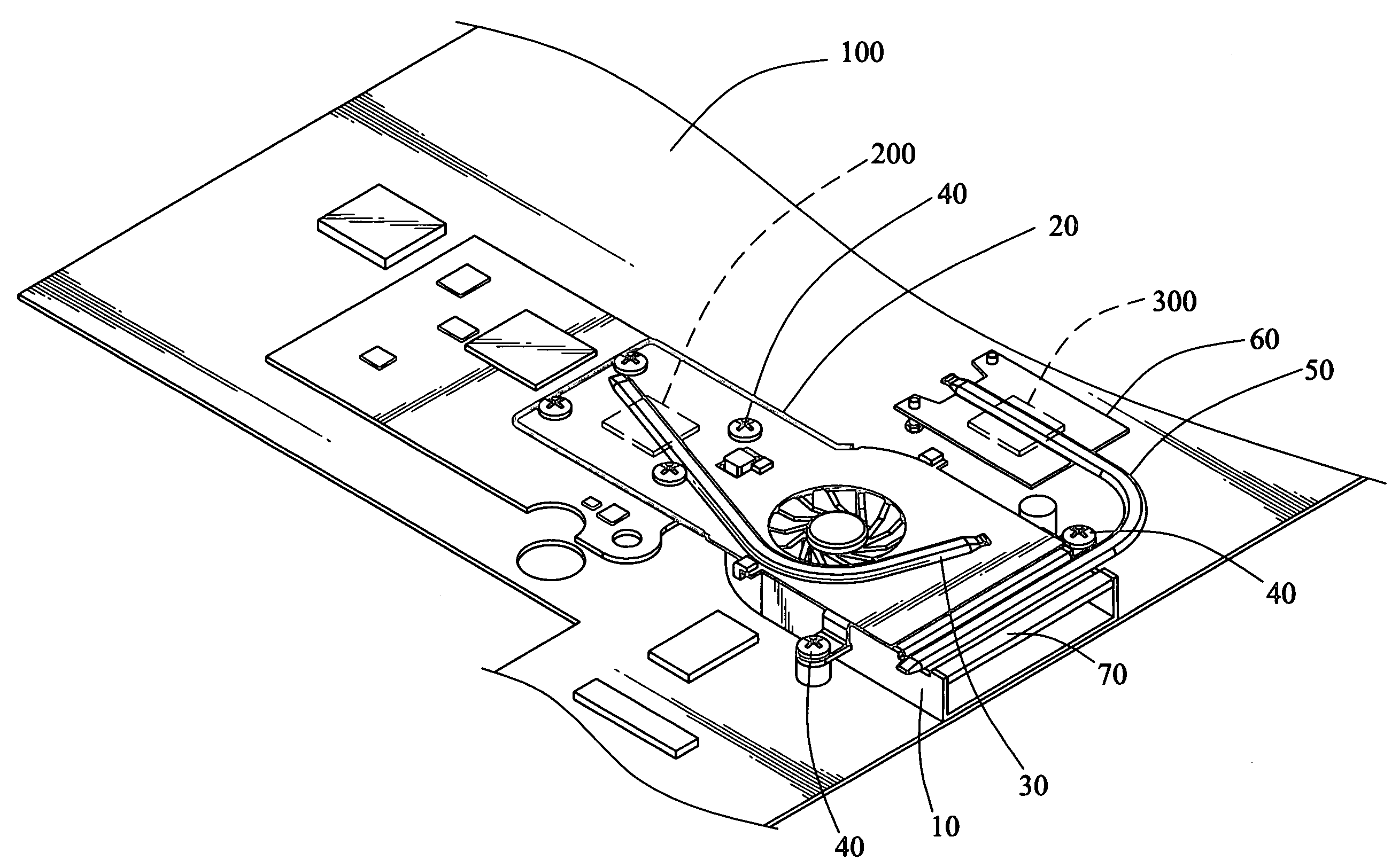
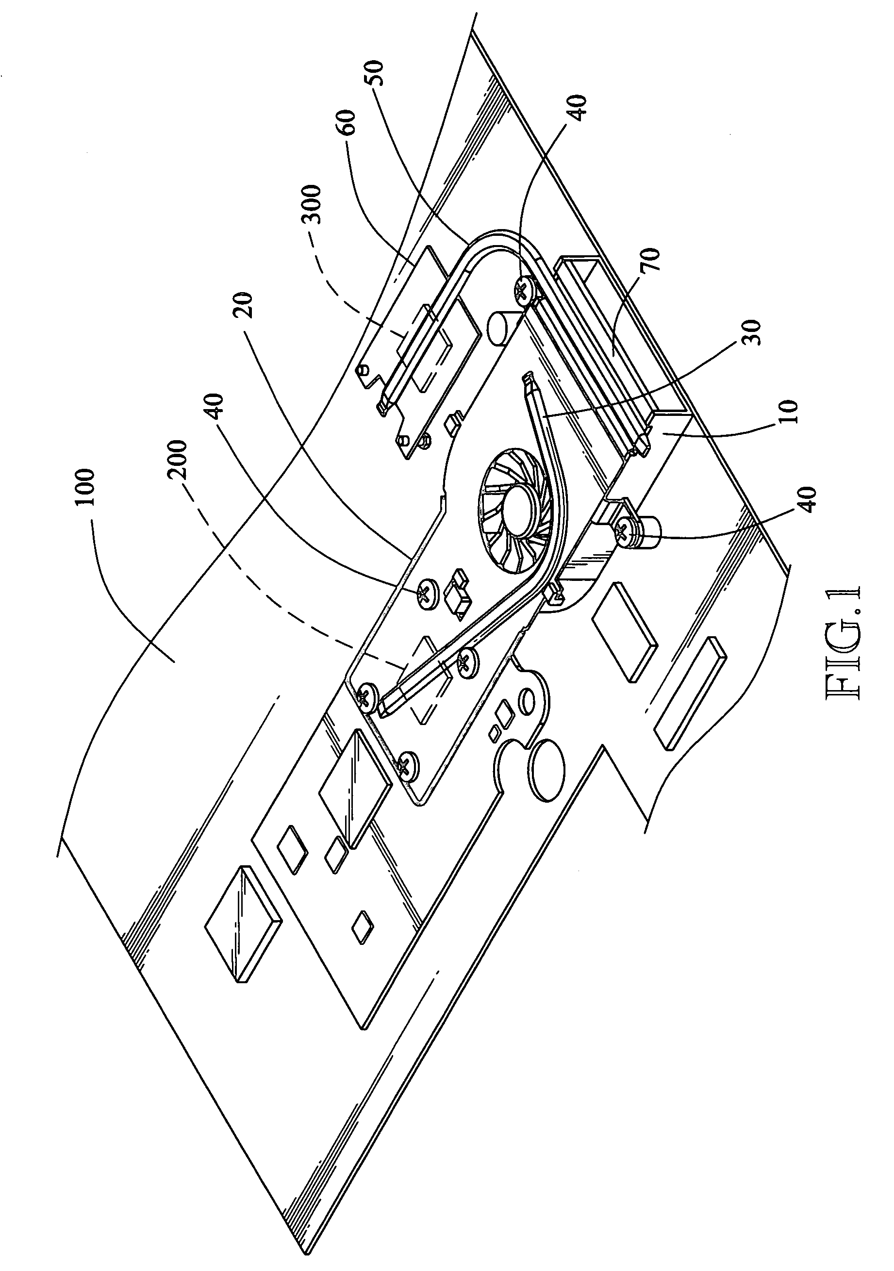
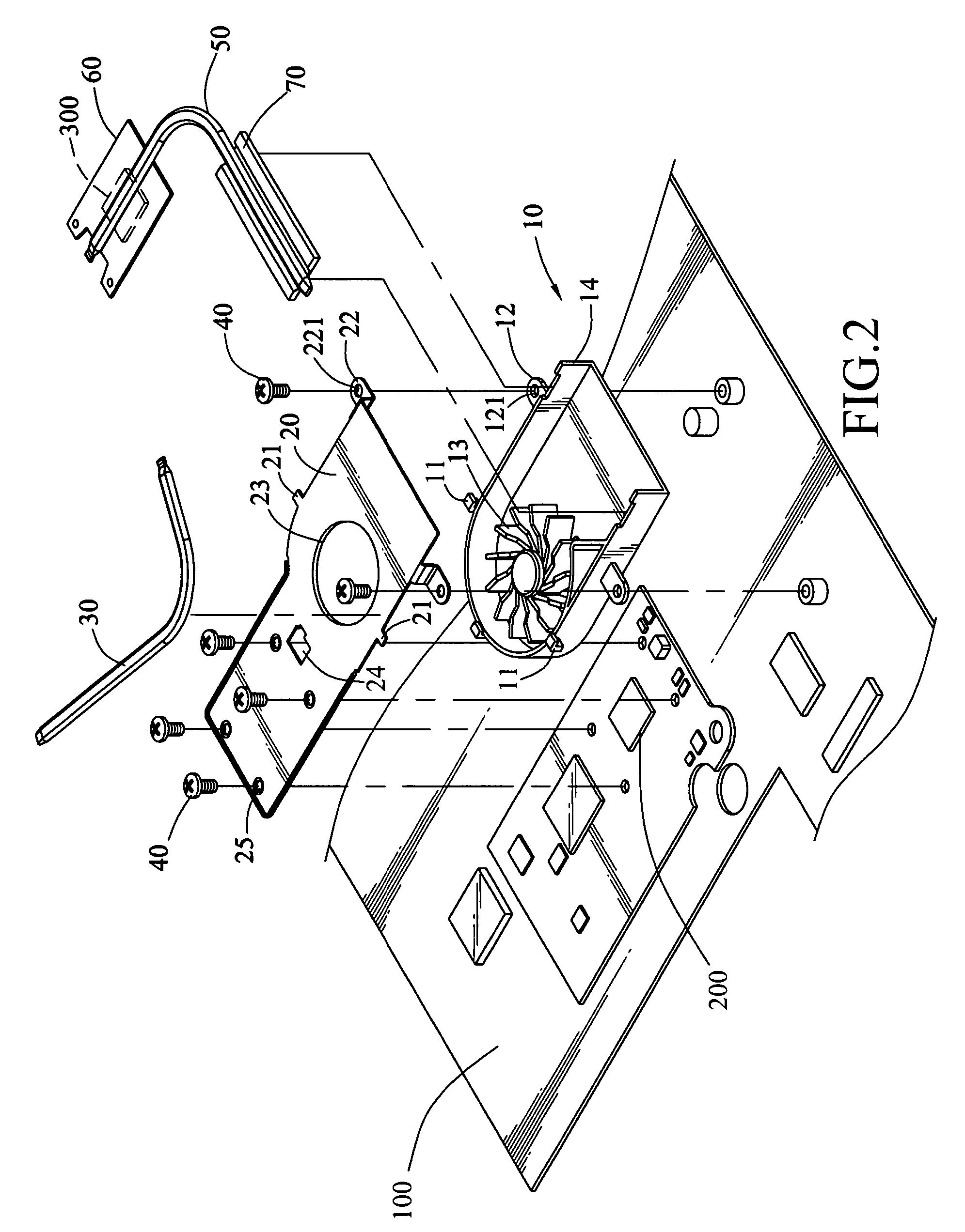
[0019]As shown in FIG. 1, it is a view of the heat sink module of the present invention. The motherboard 100 has many electronic elements thereon, but the temperature of these electric elements is relatively raised due to high speed computing. However, there is somewhat a limitation to the operation temperature of each of the electric elements. For the electric elements, high temperature affects operation efficiency, and in some severe circumstances, high temperature may further damage or even burn the electrical elements. Therefore, the heat sink has become crucial in product design. In the drawing, the heat sink function is illustrated by two electrical elements for the heat source, for example, a first chip 200 and a second chip 300. The first chip 200 is covered with a heat sink plate 20 made of a material with high temperature resistance and preferable heat conductivity, for instance aluminum or an aluminum alloy. And the second chip 300 is also covered with a first heat sink 6...

second embodiment

[0022]Please refer to FIG. 5, which is a view of the heat sink module according to the present invention. If the position of the heat source is different from that of the first chip 200 as shown in FIG. 1, the second heat pipe 50 can be used to conduct heat from the farther heat source to the second heat sink plate 70 of the fan set 10 as shown in FIG. 5. The first heat sink 60 is fixed on the motherboard 100, so that the second chip 300 is sandwiched between the first heat sink 60 and the motherboard 100. A second heat pipe 50 is disposed on the first heat sink 60 and extends to the heat sink plate 20 on the fan set 10. The heat from the second chip 300 is conducted to the second heat sink 70 of the fan set 10 through the second heat pipe 50, and then dissipated by the fan set 10. Thus, the problem of the position of the heat source is solved.


PUM


Abstract

A heat sink module includes a fan set and a heat sink plate. The fan set is integrated as a whole, reducing manufacture time, and the material of the fan set is plastic, thus reducing the weight as well. Due to the hook design of the fan set and the ear design of the heat sink plate, the number of screws is reduced. Furthermore, the screws pass through the first lug of the heat sink plate and the second lug of the fan set, so that the heat sink plate and the fan set are fixed on the motherboard, and thereby the number of the parts to be fixed by screws is reduced. Heat from the heat source on the motherboard is conducted to the fan set to be dispersed through the heat sink plate extending to the heat source and covering the fan set.

Description

BACKGROUND OF THE INVENTION[0001]1. Field of Invention[0002]The present invention relates to a heat sink device and more particularly to a heat sink module having the design of reducing the screws and being suitable for dissipating heat produced by a chip on the motherboard.[0003]2. Related Art[0004]The development of information science and technology enables the computer to be widely used. As the computing function and speed of the electric elements, such as the central processing unit and the display chip, are enhanced, the high speed and large amount of computing results in a problem of high temperature accordingly. However, there is somewhat a limitation to the operation temperature of each of the electric elements. For the electric elements, high temperature affects operation efficiency, and in some severe circumstances, high temperature may further damage or even burn the electrical elements. Therefore, the heat sink has become crucial in product design. In order to make the ...

Claims


Application Information

Patent Timeline
Patent Type & Authority Patents(United States)
IPC IPC(8): H05K7/20
CPCG06F1/203H01L23/427H01L23/467H01L2924/0002H01L2924/00
Inventor CHENG, YI-LUNLIN, CHUN-LUNGWANG, FENG-KU
Owner INVENTEC CORP
Why Eureka
Try Eureka