DC-DC converter

a converter and diode technology, applied in the direction of dc-dc conversion, power conversion systems, instruments, etc., can solve the problems of damage to the diode b>11/b>, excessive output current flow, and small current consumption, so as to reduce power consumption when overloaded

Inactive Publication Date: 2008-03-04
SANKEN ELECTRIC CO LTD
View PDF5 Cites 50 Cited by
  • Summary
  • Abstract
  • Description
  • Claims
  • Application Information

AI Technical Summary

Benefits of technology

[0025]It is an object of the present invention to provide a DC-DC converter capable of reducing power consumption when overloaded without affecting activating time.
[0027]According to the present invention, at the time of activation, the control circuit is activated by the first activation current of the activation circuit. Moreover, when the switching element is intermittently turned on and off when overloaded after the activation, the control circuit is activated by the second activation current which is smaller than the first activation current. Therefore, an initial activating time and an intermittent period when overloaded can be separately set. Thus, it is possible to extend the intermittent period when overloaded without affecting the activating time period, and to reduce power consumption when overloaded.

Problems solved by technology

In particular, when the load 18 is short-circuited or the like, the output current is increased, which may damage the diode 11 and the like.
However, when the control circuit 8 is stopped, the current consumption is very small.
On account of this, the switching operation cannot be immediately stopped, which may cause a flow of an excessive output current.
This causes a problem that it may be impossible to satisfy a regulation on the activating time period, which is provided for specifications of the DC-DC converter.

Method used


Image

  • DC-DC converter
  • DC-DC converter
  • DC-DC converter

Examples


embodiment 1

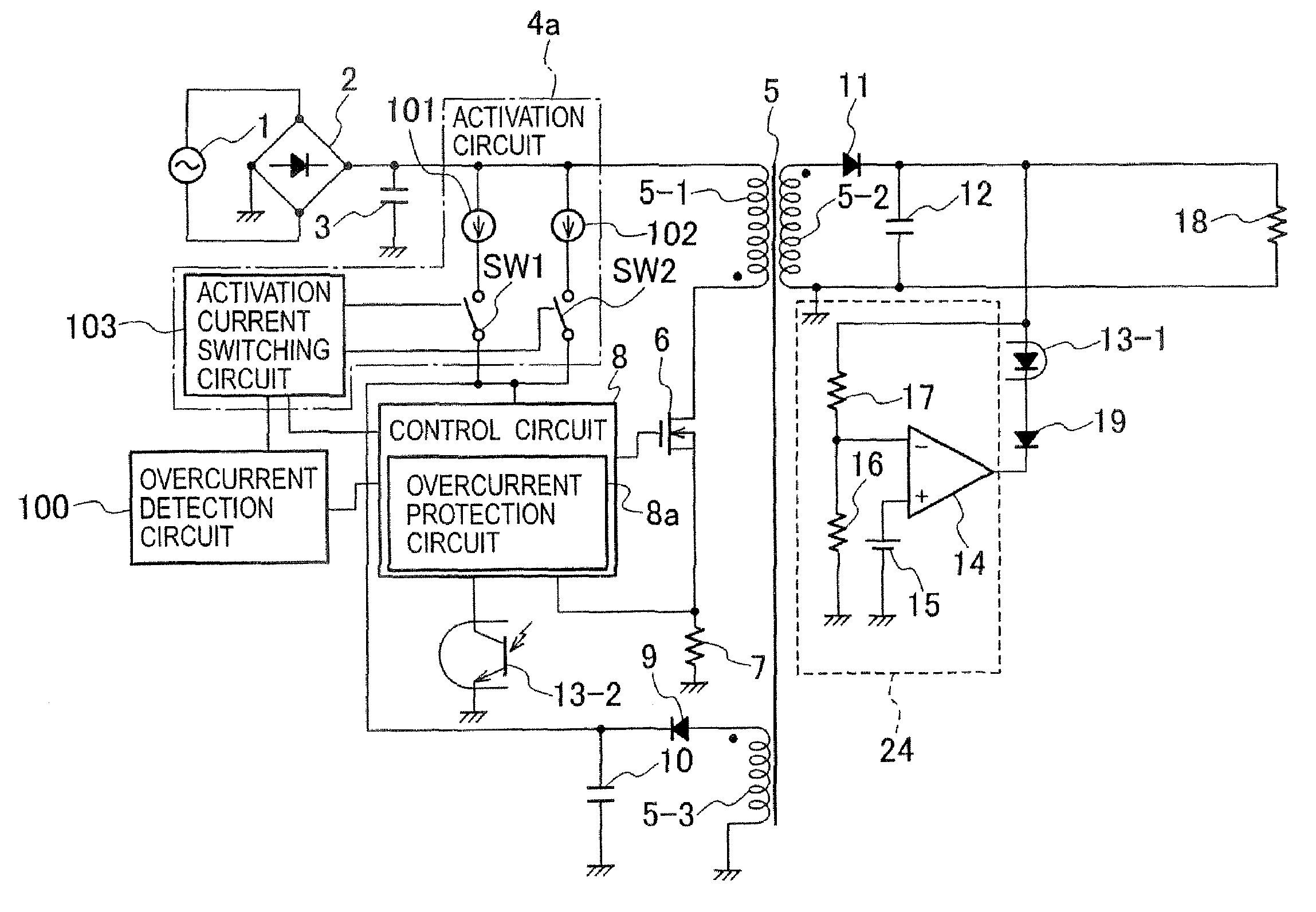
[0044]FIG. 4 is a circuit configuration diagram of a DC-DC converter according to embodiment 1 of the present invention. The DC-DC converter is a flyback DC-DC converter, which is operated by inputting a DC voltage obtained by rectifying and smoothing output from an AC power supply 1 by use of a full-wave rectifier 2 and a capacitor 3.

[0045]The DC-DC converter includes: an activation circuit 4a; a transformer 5 having a primary winding 5-1, a secondary winding 5-2 and a tertiary winding 5-3; a switching element 6 formed of, for example, a MOSFET; a resistor 7 for detecting an input current; a control circuit 8 for controlling the turning on and off of the switching element 6; a first rectifying and smoothing circuit including a diode 11 and a capacitor 12; a second rectifying and smoothing circuit including a diode 9 and a capacitor 10; an output voltage detection circuit 24; a photocoupler 13 including a light emitting diode 13-1 and a phototransistor 13-2; and an overcurrent detec...

embodiment 2

[0065]As is clear from the waveform of the voltage V10 of the capacitor 10 in FIG. 5, the equivalent operations as those in embodiment 1 described above can be performed by monitoring the voltage V10 of the capacitor 10. A DC-DC converter according to embodiment 2 controls an intermittent period according to the voltage V10 of the capacitor 10.

[0066]FIG. 7 is a circuit configuration diagram of the DC-DC converter according to embodiment 2 of the present invention. The DC-DC converter is configured by changing the activation circuit 4a in the DC-DC converter of embodiment 1 to an activation circuit 4b and by adding an overcurrent detection circuit 25. In the following description, differences from embodiment 1 will be mainly described.

[0067]The activation circuit 4b includes a first constant current circuit 101, a second constant current circuit 102, a first switch SW1, a second switch SW2, resistors 110 and 111, a reference power supply 112, a hysteresis comparator 113, resistors 11...

embodiment 3

[0085]FIG. 10 is a circuit configuration diagram of a DC-DC converter according to embodiment 3 of the present invention. In the DC-DC converter, a third rectifying and smoothing circuit including a diode 220 and a capacitor 221, which are connected to the tertiary winding 5-3, is added to the DC-DC converter in embodiment 1. The overcurrent detection circuit 100 detects an overcurrent by use of a current flowing through the switching element 6. The activation current switching circuit 103 is configured to generate first and second activation currents by use of a signal from the overcurrent detection circuit 100, a voltage outputted from the second rectifying and smoothing circuit, and a voltage outputted from the third rectifying and smoothing circuit. Moreover, FIG. 10 shows specific circuit examples of the first and second constant current circuits 101 and 102, the first and second switches SW1 and SW2, the activation current switching circuit 103, and the overcurrent detection c...


PUM


Abstract

A DC-DC converter of the present invention includes: an activation circuit which activates a control circuit for controlling a turning on and off of a switching element; a second rectifying and smoothing circuit which supplies an output voltage, as a power supply, to the control circuit, the output voltage being obtained by rectifying and smoothing a voltage in a tertiary winding of a transformer; an overcurrent protection circuit which limits an output current to be supplied to a load when overloaded; an overcurrent detection circuit which detects that the load is in an overcurrent state, and which outputs a detection signal during a period when the overcurrent protection circuit is operated; and an activation current switching circuit which switches outputs from the activation circuit.

Description

BACKGROUND OF THE INVENTION[0001]1. Field of the Invention[0002]The present invention relates to a DC-DC converter, and more particularly to a technology for protecting a circuit by intermittently turning on and off a switching element when overloaded.[0003]2. Description of the Related Art[0004]FIG. 1 is a diagram showing a circuit configuration of a conventional flyback DC-DC converter. The DC-DC converter is operated by inputting a DC voltage obtained by rectifying and smoothing output from an AC power supply 1 by use of a full-wave rectifier 2 and a capacitor 3.[0005]The DC-DC converter includes: an activation circuit 4; a transformer 5 having a primary winding 5-1, a secondary winding 5-2 and a tertiary winding 5-3; a switching element 6 formed of, for example, a MOSFET; a resistor 7 for detecting an input current; a control circuit 8 for controlling a turning on and off of the switching element 6; a first rectifying and smoothing circuit including a diode 11 and a capacitor 12...

Claims


Application Information

Patent Timeline
Patent Type & Authority Patents(United States)
IPC IPC(8): H02H7/122H02M3/335
CPCH02M1/32H02M3/33507H02M1/36
Inventor UCHIDA, AKIHIRO
Owner SANKEN ELECTRIC CO LTD
Why Eureka
Try Eureka