X-ray computed tomography apparatus for fast image acquisition

a computed tomography and image acquisition technology, applied in the field of x-ray computed tomography apparatus, can solve the problems of reducing image quality and dose efficiency relative to computed tomography systems of the third generation, maximum rotation speed, and limiting the rotation speed of the rotary frame. achieve the effect of improving image quality and fast image acquisition

Inactive Publication Date: 2008-03-04
SIEMENS AG
View PDF12 Cites 11 Cited by
  • Summary
  • Abstract
  • Description
  • Claims
  • Application Information

AI Technical Summary

Benefits of technology

[0014]An object of the present invention is to provide a computed tomography apparatus for fast image acquisition that provides an improved image quality relative to known computed tomography apparatus systems of the fifth generation.
[0016]The x-ray computed tomography apparatus thus can be designed like the known computed tomography systems of the fifth generation with regard to the generation and the detection of the x-ray radiation, or designated for electron beam computed tomograph (EBCT). In contrast to conventional designs of such computed tomography systems, the inventive apparatus additionally has the aforementioned rotating carrier frame on which are arranged one or more shaping elements for influencing one or more beam parameters of the x-ray beam. The carrier frame that can be rotated around the system axis (z-axis) is moved in synchronization with the movement of the x-ray focus on the target. In this manner a scan speed is reached that is substantially increased relative to x-ray computed tomography systems of the third generation, since the carrier frame carries no heavy parts, in particular neither an x-ray tube nor the x-ray detectors. Relative to the carrier frame of a computed tomography apparatus of the third generation, the weight can be reduced by a factor of 100, such that a distinct increase in the rotation (and thus scan) speed can be achieved without reduction of the image quality. Moreover, a significant image improvement is achieved relative to known computed tomography systems of the fifth generation since the shaping elements rotating with the x-ray focus enable an optimal beam shaping and / or suppression of scatter radiation.
[0019]In all cases, in the inventive computed tomography apparatus an optimal adaptation of the one or more shaping elements to the current x-ray focus is enabled since the shaping elements move in synchronization with the x-ray focus due to the rotating carrier frame. Moreover, the use of a phi collimator and / or bowtie filter is possible in this manner as with computed tomography systems of the third generation. The lamellae or walls of a scattered-ray grid arranged on the carrier frame can be optimally aligned to the x-ray focus. Both measures improve the image quality and reduce the x-ray radiation to which the patient is exposed. In this case, due to the rotation movement the individual cells of the scattered-ray grid also do not have to be adapted to the sub-division of the x-ray detector. Rather, the static relation between the scattered-ray grid and the x-ray detector can be utilized.
[0020]Given the arrangement of a Z-collimator on the carrier frame, a distortion of the projection of the x-ray beam on the detector surface can be prevented by suitable shaping of the lamellae of this Z-collimator. For this purpose, the borders of both limiting lamellae of the Z-collimator that are turned away from the x-ray focus can be adapted to the curve of the outer boundaries of the x-ray detector such that the projection edges of the x-ray beam on the detector surface follow this curve.
[0021]The light carrier frame in accordance with the invention can also be used for further improvement of a computed tomography apparatus as is known, for example, from U.S. Pat. No. 4,606,061. In this computed tomography apparatus, the moving x-ray focus is generated by a laser beam that strikes an electron source ring arranged at a slight distance from the annular target. There the laser beam produces electrons that are accelerated in the direction of the target by a voltage applied between the target and the electron source ring, and generate x-ray radiation at the target upon impact. The rotation of the focus around the examination volume is achieved by movement of the laser beam over the electron source ring that can be generated by a scan mechanism. In the present embodiment of such a computed tomography apparatus, the device for injecting (coupling) the laser beam into the electron source ring is also mounted on the carrier frame, in the simplest case a circular cover of the electron source ring with an injection window. In this manner it can be ensured that the laser beam always is incident at the correct position on the electron source ring. This reduces the danger of an error function or damage due to unwanted light reflections. In a version of this embodiment, a converging lens is arranged at the entrance window, with which the laser beam is additionally focused on the electron source ring. This increases the photo-emission efficiency.

Problems solved by technology

In the meantime, for reasons of mechanical stability and safety in computed tomography systems of the third generation, a limit has been reached that no longer allows a distinct increase of the rotation speed of the rotary frame due to the masses that must be moved and the high acceleration forces resulting therefrom.
However, here as well significant forces that limit the maximum rotation speed act on the x-ray tube given a further increase of the rotation speed of the rotary frame.
Due to the absence of a rotating x-ray tube, the aforementioned embodiments of computed tomography systems of the fifth generation achieve significantly higher scan speeds, but suffer from a reduced image quality and dose efficiency relative to computed tomography systems of the third generation.
This is primarily a result of the limited possibilities for influencing beam parameters of the x-ray beam.
In the known computed tomography systems of the fifth generation with a stationary scattered-ray grid, this cannot be realized with justifiable expense.
This banana-shaped beam profile on the detector can be avoided only when the Z-collimator is opened further, but this reduces the dose efficiency.
This reduces the detector efficiency and the image quality and leads to increased partial volume effects.

Method used


Image

  • X-ray computed tomography apparatus for fast image acquisition
  • X-ray computed tomography apparatus for fast image acquisition
  • X-ray computed tomography apparatus for fast image acquisition

Examples


Embodiment Construction

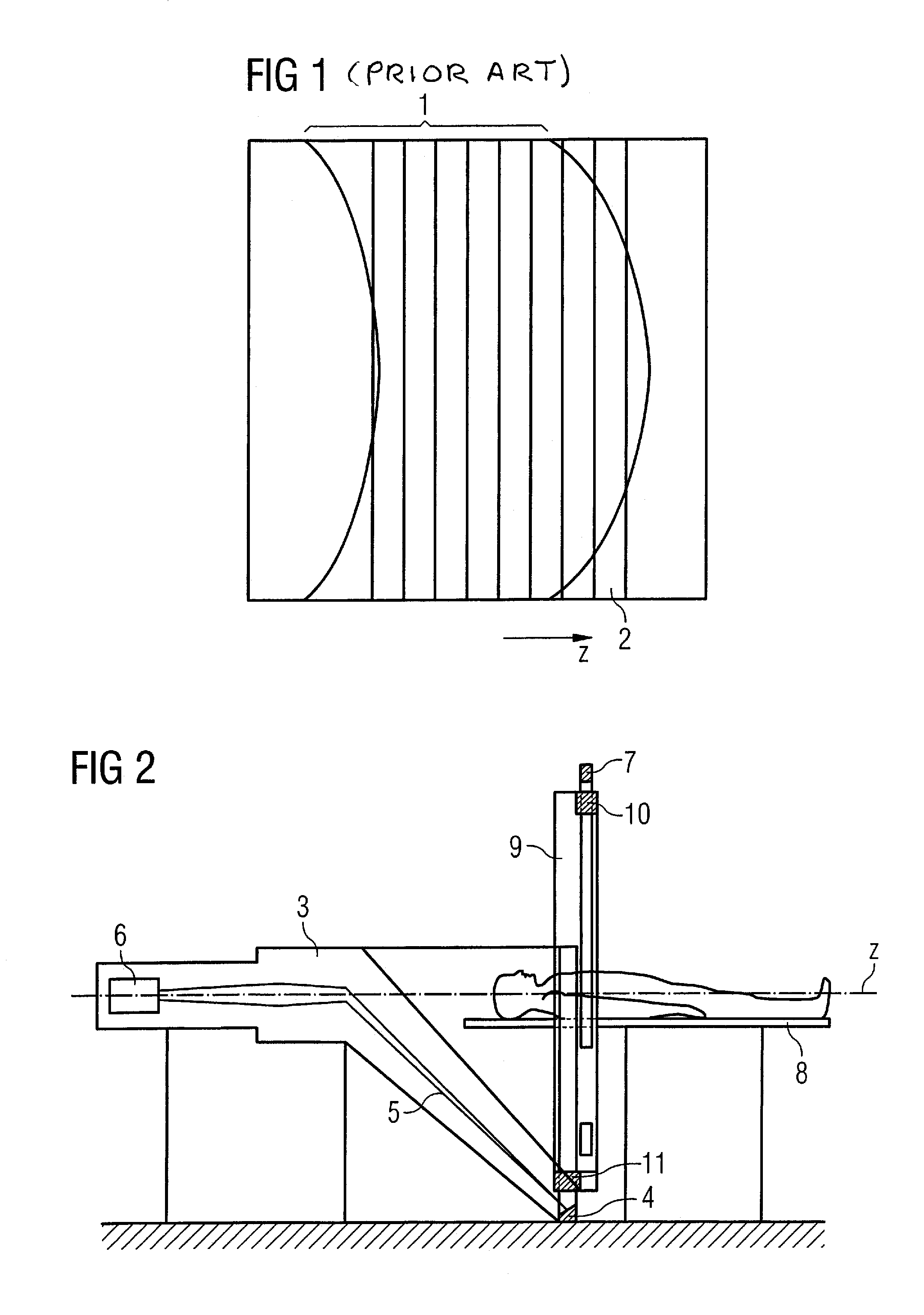
[0033]FIG. 1 was already explained in connection with the discussion of the prior art, and shows the banana-shaped distortion of the projection 1 of the x-ray beam on the detector lines 2 of an 8-line x-ray detector in known computed tomography systems of the 5th generation. This distortion materializes due to the annular Z-collimator used in these systems.

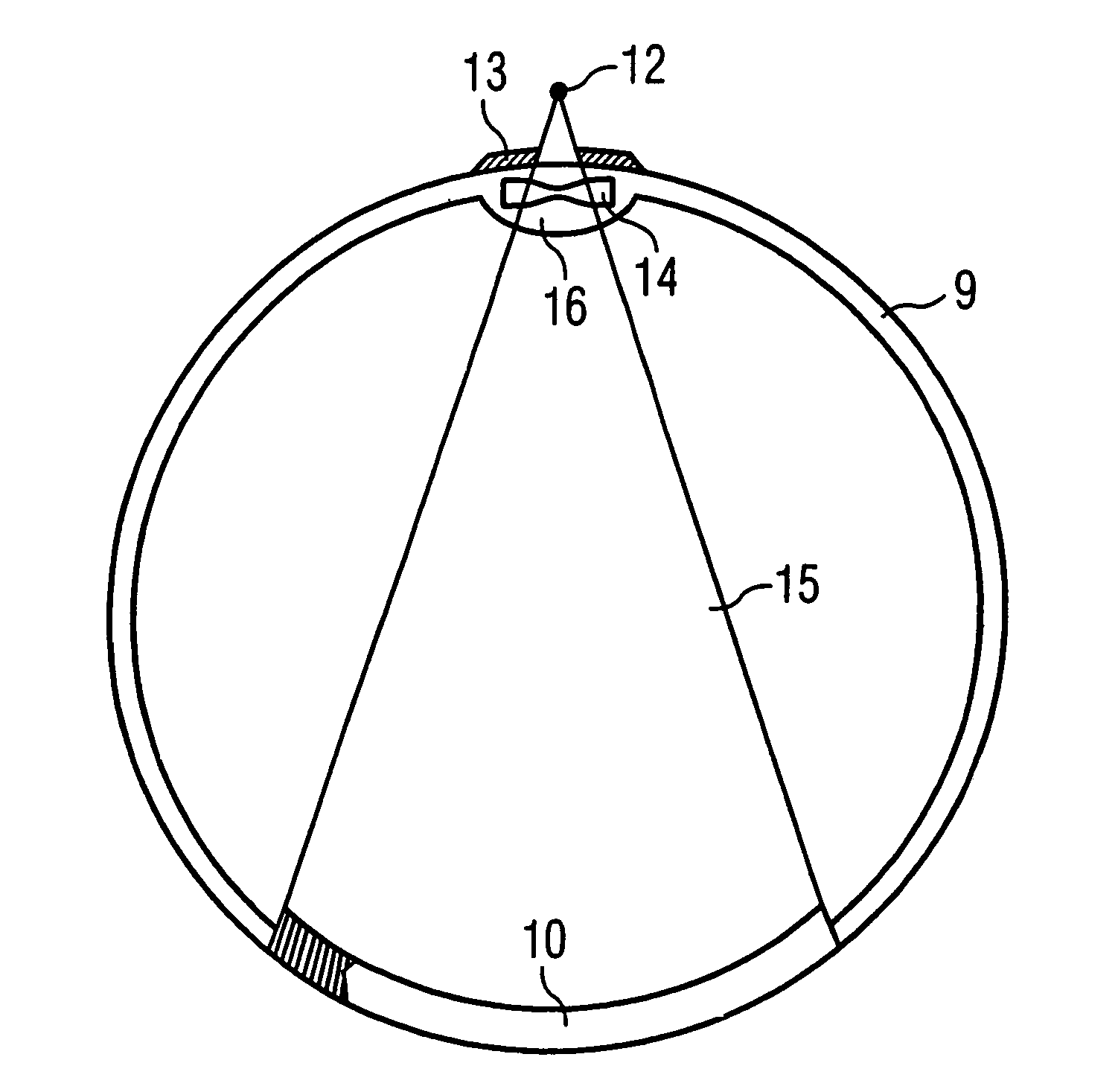
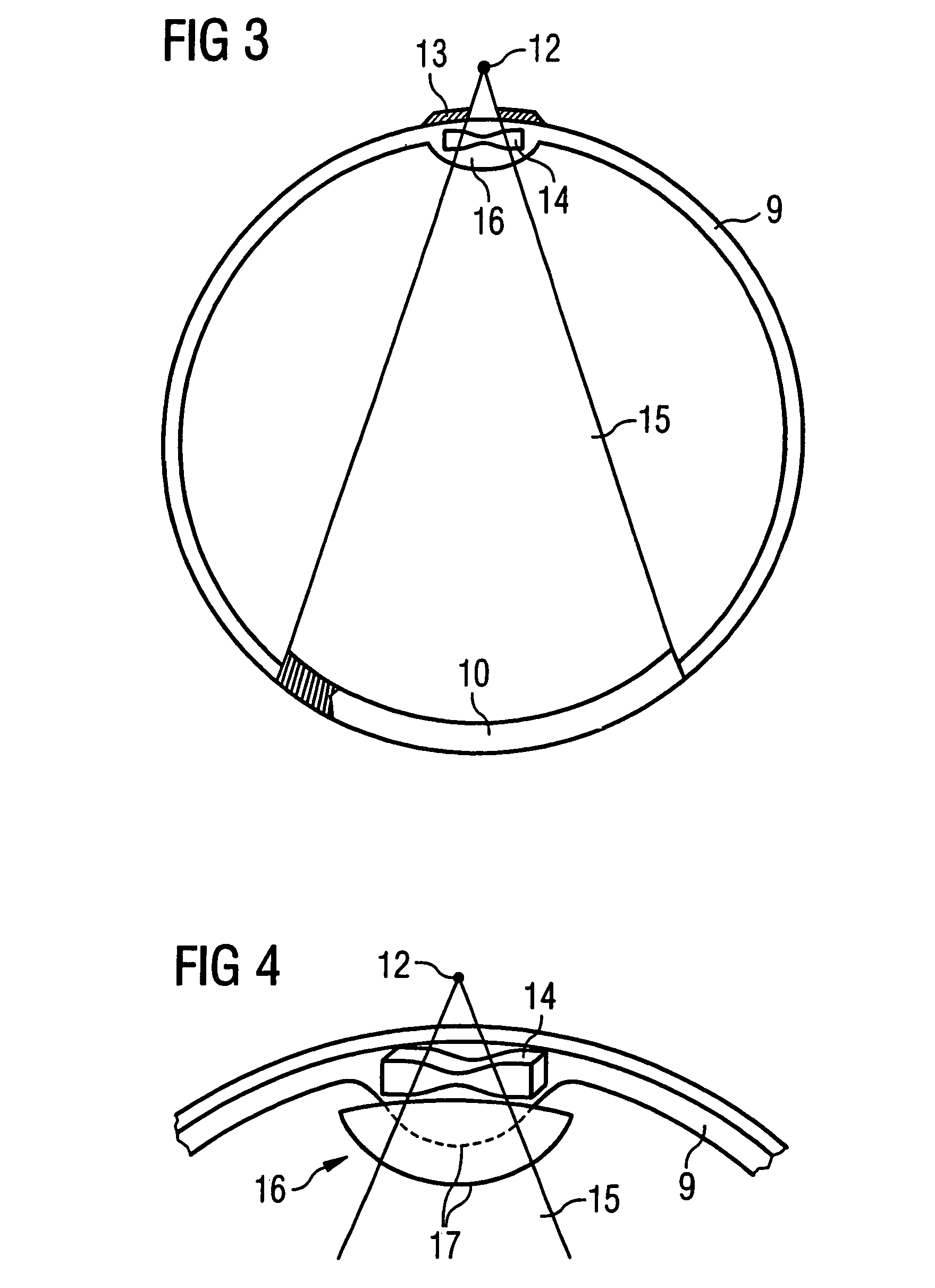
[0034]Such a distortion can be avoided with the inventive computed tomography apparatus by suitable shaping of the lamellae of the Z-collimator on the rotating carrier frame. FIG. 2 shows a schematic representation of an exemplary design of a computed tomography apparatus according to the present invention. In this example, the apparatus has an x-ray generating device 3 with a target 4 that extends as a partial ring through approximately 210° around the examination volume. The x-ray focus on the target 4 (which, for example, is composed of tungsten) is generated with an electron beam 5 that is focused from an electron gun 6 onto a...


PUM


Abstract

An x-ray computed tomography apparatus has a stationary device (3) for generating x-ray radiation from an x-ray focus that moves around the examination volume on a target that at least partially surrounds an examination volume of the apparatus in one plane. From the x-ray focus an x-ray beam is directed through the examination volume onto respective, momentarily opposite detector elements of a stationary x-ray detector that at least partially surrounds the examination volume. One or more shaping elements for influencing one or more beam parameters of the x-ray beam are arranged between the target and the detector elements. One or more of the shaping elements is / are arranged on a carrier frame that can rotate around a system axis in synchronization with the movement of the x-ray focus. The shaping elements rotating with the x-ray focus enable an optimal beam shaping and / or suppression of scatter radiation.

Description

BACKGROUND OF THE INVENTION[0001]1. Field of the Invention[0002]The present invention concerns an x-ray computed tomography apparatus of the type having a stationary device for generation of x-ray radiation from an x-ray focus that moves around the examination volume on a target that at least partially encloses an examination volume of the apparatus in one plane, wherein an x-ray beam is directed from the focus through the examination volume onto respective, temporarily opposite detector elements of a stationary x-ray detector that at least partially surrounds the examination volume, and wherein one or more shaping elements that influence one or more beam parameters of the x-ray beam are arranged between the target and the detector elements.[0003]2. Description of the Prior Art[0004]Computed tomography systems are used in medical imaging to acquire images of the inside of the body of a patient. A computed tomography apparatus includes, among other things, a device for generating x-r...

Claims


Application Information

Patent Timeline
Patent Type & Authority Patents(United States)
IPC IPC(8): H05G1/60A61B6/00G21K1/04
CPCA61B6/032A61B6/4275A61B6/4028G01N23/046G01N2223/612G01N2223/419
Inventor POPESCU, STEFAN
Owner SIEMENS AG
Why Eureka
Try Eureka