Demodulation apparatus for a network transceiver and method thereof

a network transceiver and demodulation apparatus technology, applied in the field of network transceivers for gigabit ethernet systems, can solve the problems of inability to receive signals transmitted by the transceiver, the speed of the convergence of coefficients is slower, and the determined coefficients of the devices cannot be converged to an appropriate value, so as to avoid poor performance or system divergence from interaction

Active Publication Date: 2008-03-11
REALTEK SEMICON CORP
View PDF7 Cites 5 Cited by
  • Summary
  • Abstract
  • Description
  • Claims
  • Application Information

AI Technical Summary

Benefits of technology

[0010]An object of the present invention is to provide a network transceiver and the method thereof to avoid poor performance or system divergence from interaction between devices.

Problems solved by technology

However, since the operation of the devices may have interaction to each other when determining the coefficients, the determined coefficients of the devices may not be converged to an appropriate value.
Thus, signals transmitted by the transceiver cannot be received.
It may cause serious interaction and the speed of the convergence of the coefficients thus becomes slower.
However the performance of the Gigabit Ethernet communication system may thus be degraded.

Method used


Image

  • Demodulation apparatus for a network transceiver and method thereof
  • Demodulation apparatus for a network transceiver and method thereof
  • Demodulation apparatus for a network transceiver and method thereof

Examples


Embodiment Construction

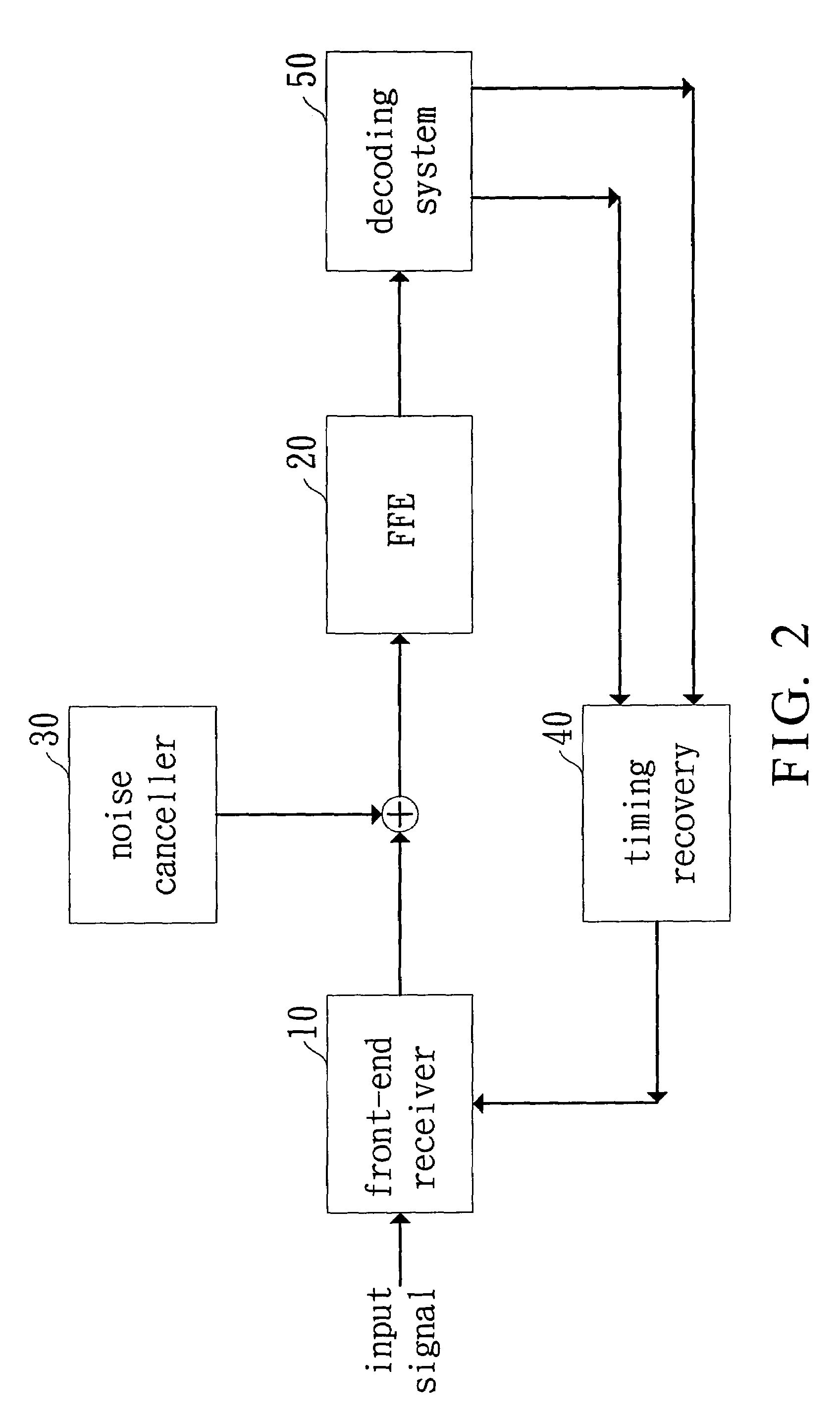
[0018]FIG. 2 shows a preferred embodiment of a receiver for a network transceiver according to the present invention. In FIG. 2, the receiver includes a front-end receiver 10, a feed-forward equalizer (FFE) 20, a noise canceller 30, a tuning recovery (TR) 40 and a decoding system 50. The front-end receiver 10 is for receiving a signal and converting the signal to a first signal in digital form with a pre-cursor component and a post-cursor component. The noise canceller 30 is coupled to the front-end receiver 10 for eliminating the noise of the first signal and thus generating a second signal. The FFE 20 is coupled to the noise canceller 30 for eliminating the pitcursor component in the second signal and thus generating a third signal. The decoding system 50 is coupled to the FFE 20 for decoding the third signal and eliminating the post-cursor component in the third signal.

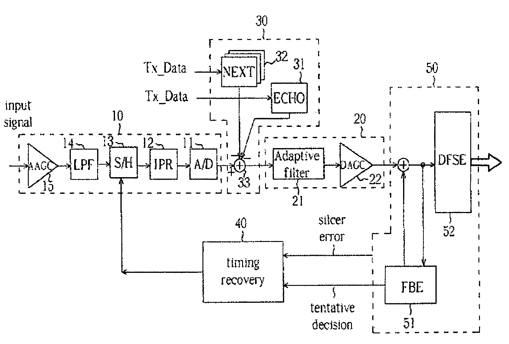
[0019]FIG. 3 is a detailed block diagram of the receiver for the network transceiver according to FIG. 2. The fr...


PUM


Abstract

A transceiver of a communication system is disclosed. The transceiver is implemented by a demodulation apparatus including a front-end receiver, a noise canceller, a feedforward equalizer (FFE) and a decoding system. The front-end receiver receives a remote signal and converts it into a first signal with a pre-cursor and a post-cursor in digital form. The noise canceller is coupled to the front-end receiver for subtracting a noise signal from the first signal and thus generates a second signal. The FFE is coupled to the noise canceller for eliminating the pre-cursor in the second signal and thus generates a third signal. The decoding system is coupled to the FFE for decoding the third signal and eliminating the post-cursor in the third signal.

Description

CROSS REFERENCE TO RELATED APPLICATIONS[0001]The present application is related to the en-pending application entitled “Demodulat ion apparatus for a network transceiver and method thereof”, application Ser. No. 10 / 687,671, filed on the same day as the present application and assigned to the same assignee, the contents of which are herein incorporated by reference.BACKGROUND OF THE INVENTION[0002]1. Field of the Invention[0003]The present invention relates to a network transceiver for Ethernet communication system and a method thereof, and more particularly, to an apparatus for estimating, equalizing and demodulating of a transceiver for Gigabit Ethernet system and a method thereof.[0004]2. Description of Related Art[0005]For an Ethernet system, a receiver to accurately receive data at a receiving-end may include the following devices: a feed-forward equalizer (FFE), a feed-back equalizer (FBE), a timing recovery (TR), an ECHO canceller, an NEXT (Near-End-Cross-Talk) canceller, etc....

Claims


Application Information

Patent Timeline
Patent Type & Authority Patents(United States)
IPC IPC(8): H04B1/10H03H17/02H03H17/06H03H21/00H04B3/06H04L7/00H04L7/02H04L25/03
CPCH03H21/0012H04L25/03038H04L7/0062H04L2025/03477H04L25/03235H04L2025/03363
Inventor LIN, HOU-WEIKUO, SHIEH-HSINGHSIEH, MENG-HANYEN, KUANG-YU
Owner REALTEK SEMICON CORP
Why Eureka
Try Eureka