Method and apparatus for blending process materials

a technology of process materials and blending methods, applied in process and machine control, non-electric variable control, instruments, etc., can solve the problems of damage to wafers, measurement errors in each of these styles, and increase with flow

Active Publication Date: 2008-03-18
MEGA FLUID SYST
View PDF57 Cites 31 Cited by
  • Summary
  • Abstract
  • Description
  • Claims
  • Application Information

AI Technical Summary

Problems solved by technology

A significant amount of time may result in the final acceptance of a liquid chemical blend, awaiting transfer, for use in a production environment.
Fluctuations may be caused by pulsations in the style of delivery mechanism used in supply equipment, from frictional losses incurred through support lines, or various head loss depending on the location of the supply equipment within a chemical processing facility.
Each of these styles of measurement incurs some form of error from the measurement.
Another form of error may be a percentage of the reading, which increases with increasing flow.
The requirements of the recipe is such that a certain level of tolerance must be maintained or the contents of the batch, with respect to the specific process, must be registered as unacceptable for use.
This process requires a specified concentration such that, over time, the material removal rate of wafers exposed is consistent: too low a concentration will not remove enough material, exposing the specific layer to be treated in successive process steps; too high a concentration may expose underlying surfaces resulting in a damaged wafer, only to be scrapped from the production lot.
If the oxidizer content varies, in the case of a below target oxidizer concentration, incomplete removal may ensue, leaving a partially planarized wafer; if the oxidizer concentration is above the specified target value, over-polished surfaces may expose and even, in some cases, damage the wafer, leading to a scrapped wafer.
In the event that a batch overshoots, some blending system architectures may not possess techniques to adjust a blend, leading to the contents being dumped to a drain line, only to restart the entire batch process.
This loss of a batch leads to lost time and wasted chemical.
In this type of system, each process material is added individually, as an automated control system is not able to discern the relative amounts of two process materials added simultaneously.
In most applications, even minor process variations may lead to significant differences in the batch of blended process materials, potentially rendering it useless for its intended application.

Method used


Image

  • Method and apparatus for blending process materials
  • Method and apparatus for blending process materials
  • Method and apparatus for blending process materials

Examples


Embodiment Construction

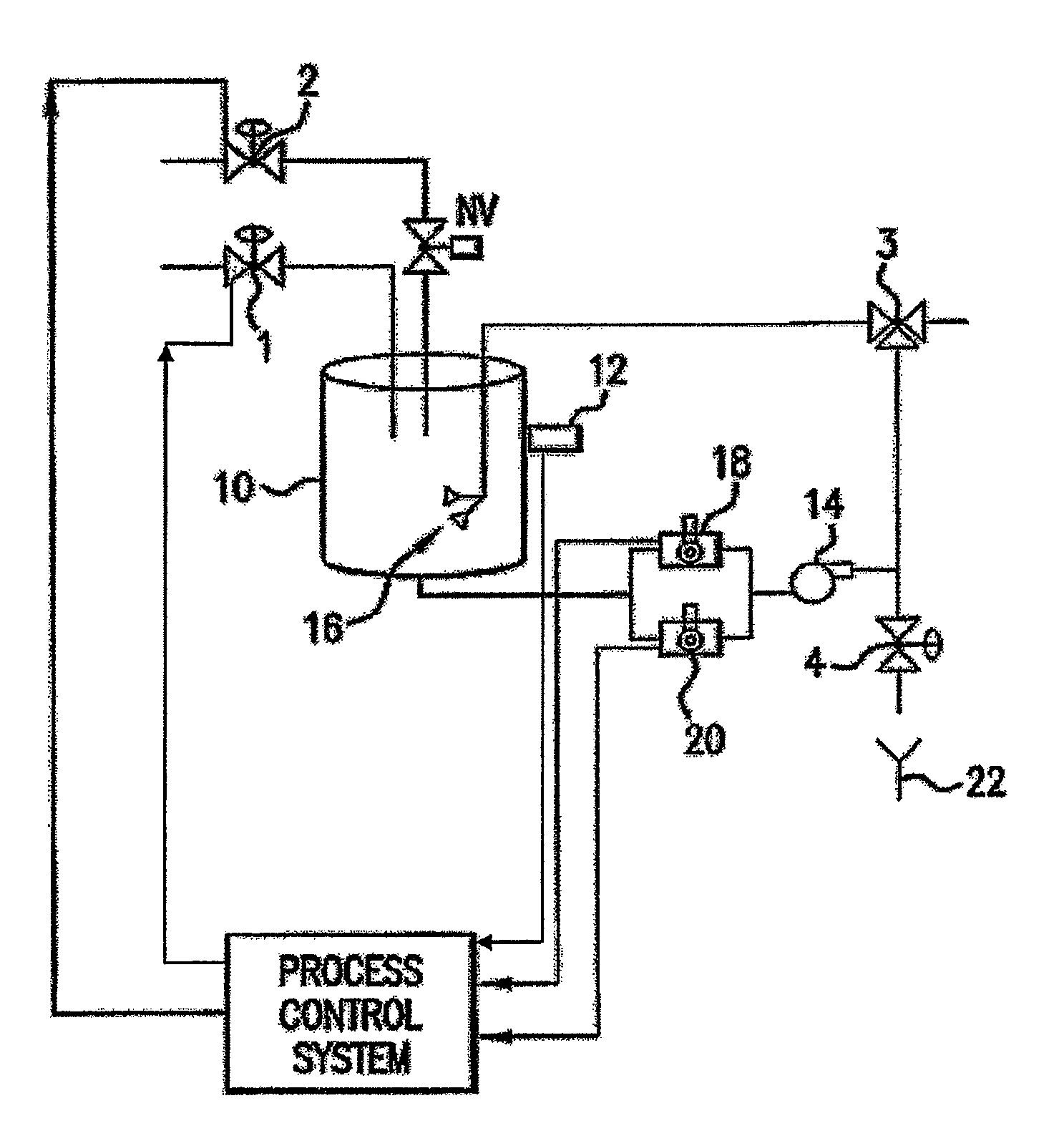
[0023]The present invention is directed towards a method for blending chemicals towards homogeneity using the metric of qualitative measurements detecting a specific parameter of chemical recipe endpoint, particularly for the dilution and blending of ultra-high purity chemicals used in the manufacture and treatment of semiconductor device substrates and overall wafer devices. This process can also be applied to the blending of abrasive colloidal suspensions used for the planarization of semiconductor device substrates.

[0024]The invention stated hereinafter, is a means to create a process, which reduces time to qualify and accept a liquid chemical batch, by analyzing and correcting a batch during the physical blending process and adjusting the rate at which a liquid chemical stream is added to the batch allowing the system to reach the required endpoint concentration.

[0025]The present invention is directed to a system for blending fixed incoming bulk concentrations of liquid chemical...


PUM

PropertyMeasurementUnit
diameteraaaaaaaaaa
wt. %aaaaaaaaaa
wt. %aaaaaaaaaa

Abstract

A method and apparatus for blending and supplying process materials. The method and apparatus are particularly applicable to the blending of ultra-high purity chemicals, the blending of abrasive slurries with other chemicals for the polishing of semiconductor wafers, and high-accuracy blending of chemicals.

Description

[0001]This application claims priority to U.S. Provisional Patent application No. 60 / 397,441 filed Jul. 19, 2002, entitled “Method and Apparatus for Blending Process Materials,” which is herein incorporated by reference in its entirety.BACKGROUND OF THE INVENTION[0002]Blended process chemicals are required, for example, in the semiconductor industry. In typical blend style systems, there are two styles of mixing, which dominate the supply system marketplace: volumetric and mass. Both are quantitative techniques, which assume that the incoming liquids are uniform streams, within a narrow range of variance to chemical concentrations based on an assay of percentage of mass of specific chemical content by total unit mass. In most cases, these small fluctuations are of a few percentage; for example, semiconductor grade hydrogen peroxide, which is typically assumed to be at thirty percent by weight, may vary from 28 to 33 percent by weight. When targeting blends requiring final contributi...

Claims


Application Information

Patent Timeline
Patent Type & Authority Patents(United States)
IPC IPC(8): B01F15/02B01F15/04B01F23/00G05D11/13
CPCB01F3/0092B01F3/04985B01F3/088G05D11/138B01F3/188B01F15/0408G05D11/132B01F3/1271B01F23/09B01F23/29B01F23/49B01F23/59B01F23/69B01F35/82B01F23/00B01F23/20B01F23/40B01F35/80
Inventor WILMER, JEFFREY A.MCALLISTER, BRIAN ALANSWAN, DANIEL A.SITTERUD, DAVID E.
Owner MEGA FLUID SYST
Why Eureka
Try Eureka