
Multilayer ceramic capacitor with terminal formed by electroless plating

a multi-layer ceramic and terminal technology, applied in the direction of fixed capacitor details, superimposed coating process, fixed capacitors, etc., can solve the problems of catastrophic failure of caps, breakdown of dielectric layers, and extremely volatile cost of palladium, so as to improve the effect of capacitance, easy to electromigrate the deposited metal, and small effect of capacitan

Inactive Publication Date: 2008-03-18
PRESIDIO COMPONENTS
View PDF9 Cites 143 Cited by
  • Summary
  • Abstract
  • Description
  • Claims
  • Application Information

AI Technical Summary

Benefits of technology

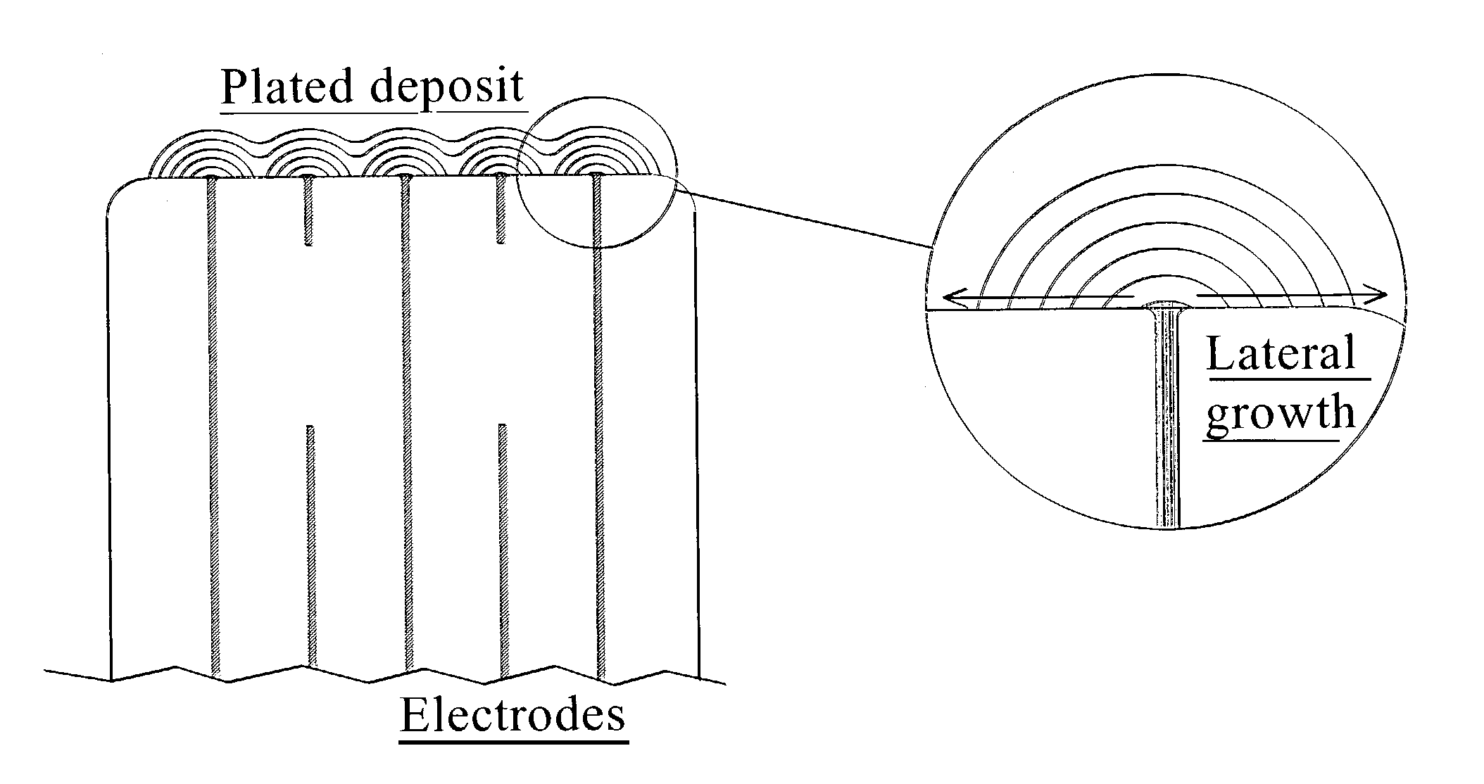
"The present invention is about a method for applying terminals to ceramic capacitors using electroless plating. This method allows for the creation of terminals that can be easily connected to other areas of the capacitor using standard plating solutions. The electroless plating process involves the growth of metal layers through lateral diffusion of metal ions, which is difficult to achieve with traditional methods of plating. The resulting ceramic capacitor has multiple layers of electrodes that are connected and can be easily further electroplated or metal layered for additional strength. The invention provides a cost-effective and reliable solution for making ceramic capacitors with plated terminals."

Problems solved by technology

In the past five years, the cost of palladium has been extremely volatile.
The heat generated will then result in a breakdown of the dielectric layer.
In ceramic capacitors, dielectric breakdown results in the catastrophic failure of the cap.
Terminals with minimal wrap-arounds tend to have lower adhesion strength and would be susceptible to peeling.
Although nickel is solderable it does not readily dissolve in molten solder as silver does.
There has been little work on an alternative method to form MLCC terminals.
Sputtered terminals do help to reduce board space; however, it is likely that this method would make parts more costly to produce.

Method used


Image

  • Multilayer ceramic capacitor with terminal formed by electroless plating
  • Multilayer ceramic capacitor with terminal formed by electroless plating
  • Multilayer ceramic capacitor with terminal formed by electroless plating

Examples


Embodiment Construction

[0109]The following description is of the best mode presently contemplated for the carrying out of the invention. This description is made for the purpose of illustrating the general principles of the invention, and is not to be taken in a limiting sense. The scope of the invention is best determined by reference to the appended claims.

[0110]Although specific embodiments of the invention will now be described with reference to the drawings, it should be understood that such embodiments are by way of example only and are merely illustrative of but a small number of the many possible specific embodiments to which the principles of the invention may be applied. Various changes and modifications obvious to one skilled in the art to which the invention pertains are deemed to be within the spirit, scope and contemplation of the invention as further defined in the appended claims.[0111]1. Method of the Present Invention for Electrodeposited Terminals (EDTs)

[0112]Electrodeposition is, in ac...


PUM

PropertyMeasurementUnit
Capacitanceaaaaaaaaaa
dielectric strengthaaaaaaaaaa

Abstract

A terminal to, most commonly, a ceramic capacitor, most commonly a multilayer ceramic capacitor (MLCC), is formed by electroless plating, also known as electroless deposition or simply as electrodeposition. In the MLCC having a multiple parallel interior plates brought to, and exposed at, at least one, first, surface, an electrically-conductive first-metal layer, preferably Cu, is electrolessly deposited upon this first surface directly in contact with, mechanically connected to, and electrically connected to, the edges of these interior plates. Lateral growth of the electrolessly-deposited first-metal is sufficient to span from exposed plate to exposed plate, electrically connecting the plates. One or more top layers, preferably one of Ni and one of Sn and Pb, are deposited, preferably by plating and more preferably by electrolytic plating, on top of the electrolessly-deposited Cu.

Description

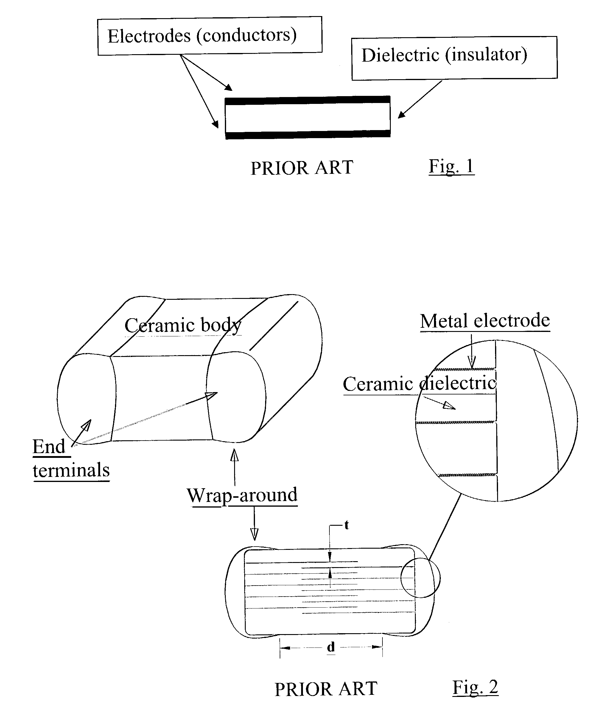
BACKGROUND OF THE INVENTION[0001]1. Field of the Invention[0002]The present invention generally concerns the fabrication of terminals on ceramic capacitors, and the terminals so fabricated.[0003]The present invention particularly concerns (i) the fabrication of terminals on and to ceramic capacitors by process of plating where lateral growth of the plating electrically connects exposed electrodes, and more preferably by process of electroless plating (also known as electroless deposition or electrodeposition); and (ii) ceramic capacitor terminals having multiple plated or electrolessly plated (also known as electrolessly deposited) layers.[0004]2. Background of the Invention[0005]2.1 General Background[0006]The capacitor is an electrical charge storage device and is one of the basic building blocks in electronics. Capacitors are made in many types including ceramic, tantalum, aluminum electrolytic, and film. The preferred embodiment of the terminal fabrication method of the present ...

Claims


Application Information

Patent Timeline
Patent Type & Authority Patents(United States)
IPC IPC(8): H01G4/228H01G4/005H01G4/232H01G4/30
CPCH01G4/2325H01G4/30H01G4/232C23C28/02C25D5/34H01G4/12
Inventor TRINH, HUNG VAN
Owner PRESIDIO COMPONENTS
Learn More