
Data transmission method and receiver

a data transmission and receiver technology, applied in the direction of radio transmission, synchronization arrangement, electrical equipment, etc., can solve the problems of wasting calculation capacity, affecting the efficiency of radio transmission, and difficulty in synchronizing, so as to maximize the energy of the signal received from the radio channel, reduce the delay of the rake receiver branch, and save calculation capacity

Inactive Publication Date: 2008-03-18
NOKIA CORP
View PDF7 Cites 0 Cited by
  • Summary
  • Abstract
  • Description
  • Claims
  • Application Information

AI Technical Summary

Benefits of technology

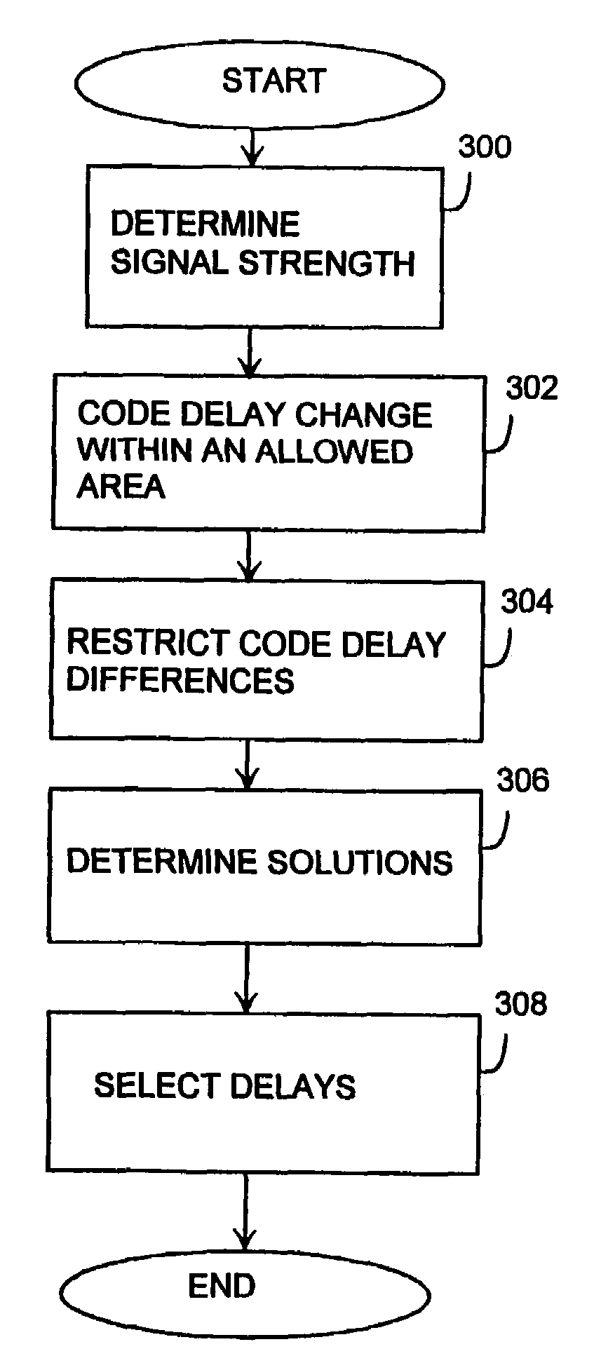
"The invention provides a method and apparatus for setting spreading code delays in RAKE receiver branches. The method involves determining the strength of a multipath propagated signal in a set of propagation delay points in the surroundings of each branch, restricting the code delay changes in each branch to exceed a predetermined value, and determining solutions for the code delays in the receiver branches that include a code delay candidate for the branch to be processed and the preceding branches. The method and apparatus offer faster and more efficient ways to set delays in RAKE receivers and save computational resources."

Problems solved by technology

A problem with the synchronizer, i.e. in setting the delays, is that code phase acquisition and code tracking require a lot of calculation capacity owing to the large number of samples.
In addition, when the impulse response does not include distinct maximum points, but the impulse response comprises a broad power maximum region, in other words a fat finger situation, achieving the synchronization is difficult on the basis of an impulse response determined from a signal component received by one branch in accordance with the prior art and in general some of the energy of the received signal is lost.

Method used


Image

  • Data transmission method and receiver
  • Data transmission method and receiver
  • Data transmission method and receiver

Examples


Embodiment Construction

[0023]The following example describes the preferred embodiments of the invention in an UMTS system (Universal Mobile Telecommunications System) without restricting the invention thereto.

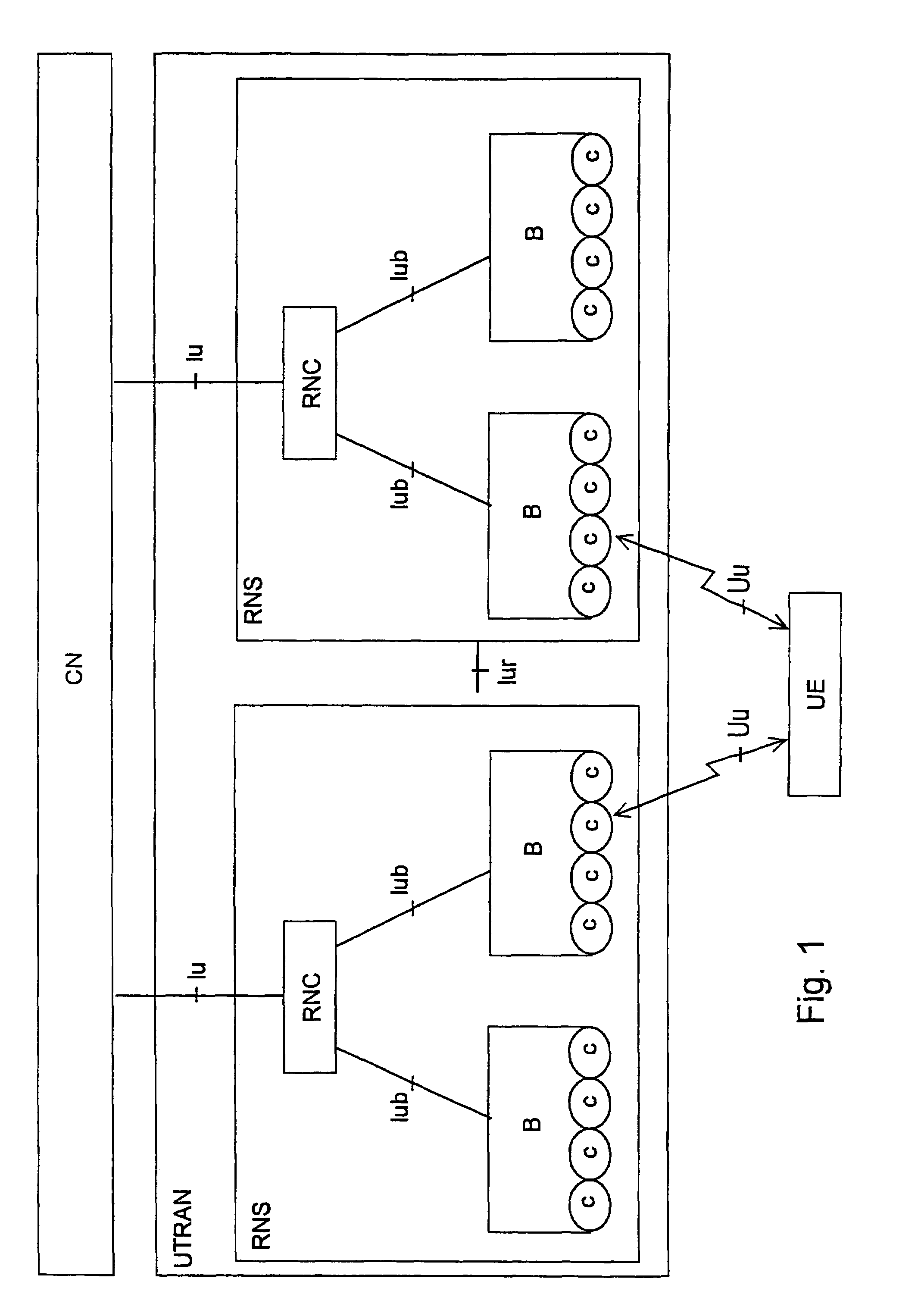
[0024]Referring to FIG. 1, the structure of a mobile system is explained by way of example. The main parts of the mobile system include a core network CN, a UMTS terrestrial radio access network UTRAN and user equipment UE. The interface between the CN and the UTRAN is referred to as lu and the air interface between the UTRAN and the UE is referred to as Uu.

[0025]The UTRAN comprises radio network subsystems RNS. The interface between the radio network subsystems RNS is called lur. An RNS comprises a radio network controller RNC and one or more nodes B. The interface between the RNC and node B is referred to as lub. The coverage area, or cell, of node B is indicated by letter C in the Figure.

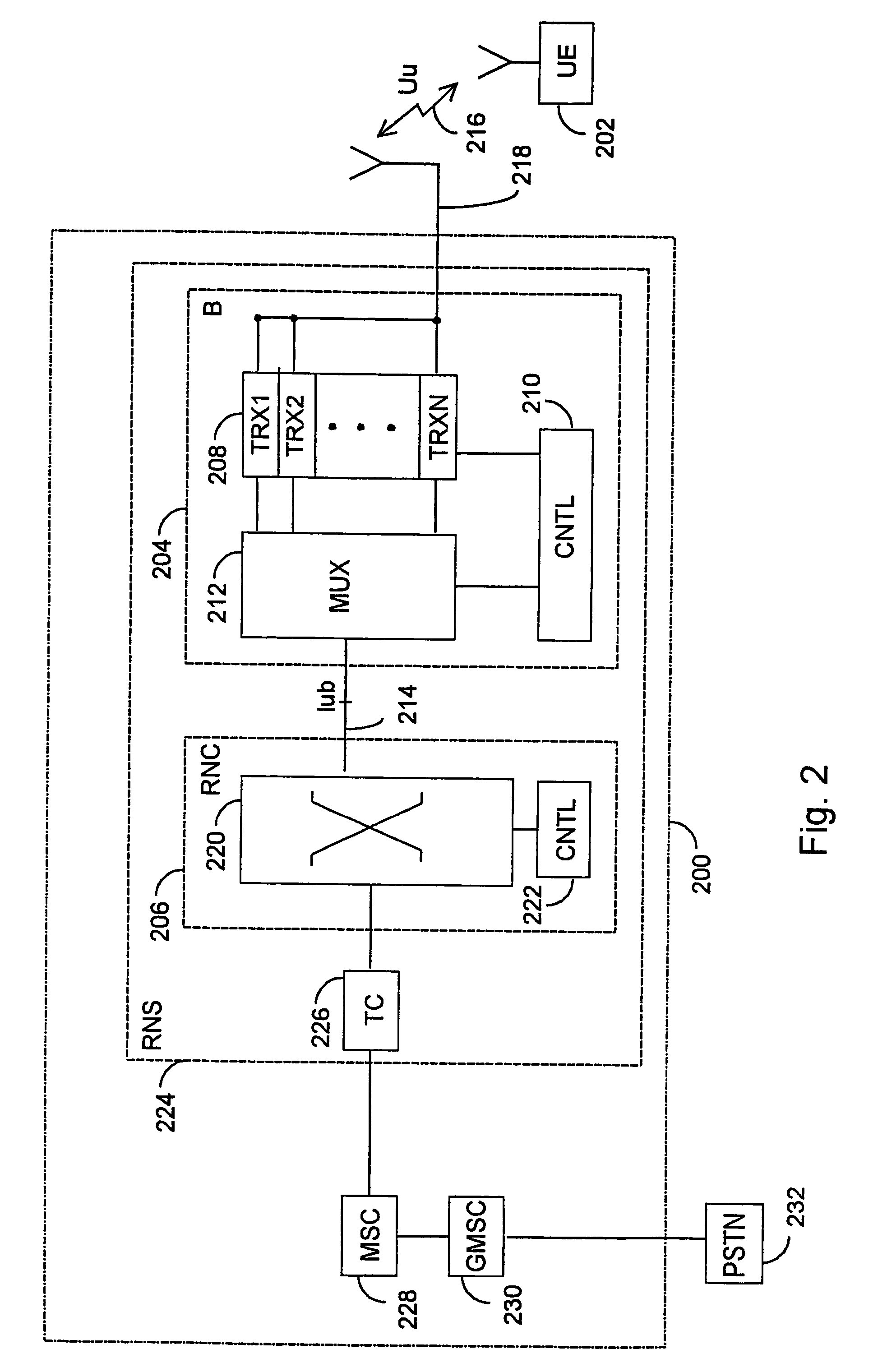
[0026]The description shown in FIG. 1 is a fairly general one, and FIG. 2 therefore shows a more detailed examp...


PUM


Abstract

A method for setting spreading code delays in RAKE receiver branches include, for instance: determining solutions for the code delays that include a code delay candidate for the branch to be processed and for in the order of delay preceding branches. The solutions maximize the sum of the signal strengths in the branch to be processed and in the preceding branches. The method also includes that the delays of the branches are selected in accordance with the last determined solution.

Description

[0001]This is a Continuation of Intenational Application No. PCT / F102 / 01015 filed Dec. 12, 2002, which designated the U.S. and was published under PCT Article 21(2) in English.FIELD[0002]The invention relates to a method for setting delays for RAKE receiver branches.BACKGROUND[0003]The propagation conditions of radio waves typically vary constantly in radio systems, such as cellular radio systems, which causes variation to the radio signal as a function of time and place, i.e. fading. The changes occurring in the channel impulse response may result from the physical changes in a medium (for instance owing to the variation of the refractive index in the medium as a function of temperature, pressure and partial pressure of vapour) or from changes in the geometry of a link (the movement of a transmitter or receiver or an obstacle on the link).[0004]One signal fading mode, fast fading, arises from multipath propagation characteristic for the cellular radio environment, wherein a signal ...

Claims


Application Information

Patent Timeline
Patent Type & Authority Patents(United States)
IPC IPC(8): H04B1/00H04B1/707H04W56/00H04W88/02
CPCH04B1/7113H04B1/7117H04B1/7115H04B1/7085
Inventor HEINILA, MARKO
Owner NOKIA CORP
Learn More