Fault current-suppressing damper topology circuit and control method thereof and converter

a topology circuit and fault current technology, applied in the field of power electronics, can solve the problems of high dv/dt stress, large system loss, high noise and harsh electromagnetic environment, and achieve the effect of effectively protecting the safety of the switch module device and the capacitor, facilitating fast fault clearing and restoration of the converter, and reducing the risk of failure curren

Active Publication Date: 2018-12-04
NR ELECTRIC CO LTD +1
View PDF13 Cites 3 Cited by
  • Summary
  • Abstract
  • Description
  • Claims
  • Application Information

AI Technical Summary

Benefits of technology

[0007]An object of the present invention is to provide a fault current-suppressing damper topology circuit and a control method thereof and a converter. The present invention is applied to a voltage source converter, and can reduce current stress of a power semiconductor switch in the converter by use of a damping resistor when a fault occurs at a DC side of the converter, thereby protecting the IGBT device, and has better performance in both economic efficiency and technicality.
[0034](1) a damper topology circuit of the present invention limits a short-circuit current peak and effectively protects the safety of a switch module device and a capacitor, in case of a DC fault of a voltage source converter;
[0035](2) the damper topology circuit enables rapid delay of a DC fault current, facilitating fast fault clearing and restoration of operation of the converter;
[0036](3) the damper topology circuit can quickly and effectively suppress a DC short-circuit current and damp the current oscillation in a multi-terminal DC system composed of modular multilevel converters, such that the safety of the device is protected and the decay time of the fault current and thus the DC outage time are greatly shortened, and economic losses and the risk of system instability caused by the outage are further reduced to a maximum extent;
[0037](4) the damper topology circuit has a self-power supply function, can be flexibly connected in series at any position of the converter, has flexible control and good independence, does not compromise the reliability of the original system, and has practical value.

Problems solved by technology

To address a high-frequency transition of an output voltage of the converter, problems such as high dv / dt stress, large system losses, high noise and harsh electromagnetic environment, may be caused.
However, all voltage source converters have an inherent defect in which a direct current (DC) fault cannot be effectively handled.
When a short-circuit fault occurs at a DC side, even if the converter has been blocked, an (alternating current) AC power supply still can inject a current to a short-circuit point via an anti-parallel diode of an IGBT so as to form a freewheel passage, so that fault clearing becomes difficult.

Method used


Image

  • Fault current-suppressing damper topology circuit and control method thereof and converter
  • Fault current-suppressing damper topology circuit and control method thereof and converter
  • Fault current-suppressing damper topology circuit and control method thereof and converter

Examples


embodiment 1

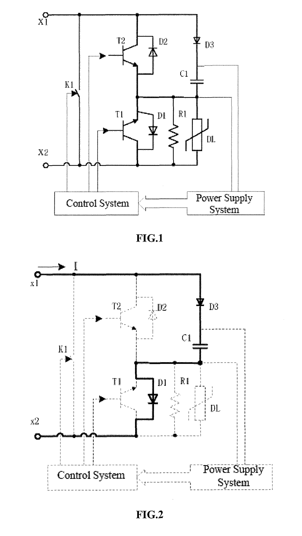
[0048]Referring to FIG. 1, a fault current-suppressing damper topology circuit includes a first switch module, a second switch module, a separate diode D3, an energy storage capacitor C1, a damping resistor R1, an arrester DL, a bypass switch K1, a power supply system, and a control system. A positive electrode of the first switch module is connected to a leading-out terminal x2 of the damper topology circuit, and a negative electrode of the first switch module is connected to a negative electrode of the second switch module. A positive electrode of the second switch module T2 is connected to a leading-out terminal x1 of the damper topology circuit. The first switch module includes a switch tube T1 and a freewheel diode D1 in anti-parallel with the switch tube T1. The second switch module includes a switch tube T2 and a freewheel diode D2 in anti-parallel with the switch tube T2. A positive electrode of the switch tube T1 is the positive electrode of the first switch module, a negat...

embodiment 2

[0051]The present embodiment provides a control method of a fault current-suppressing damper topology circuit. The fault current-suppressing damper topology circuit is the same as that of embodiment 1, and thus is not described in detail. The control system sends a control signal to cause the fault current-suppressing damper topology circuit to operate in one of five operating states below:

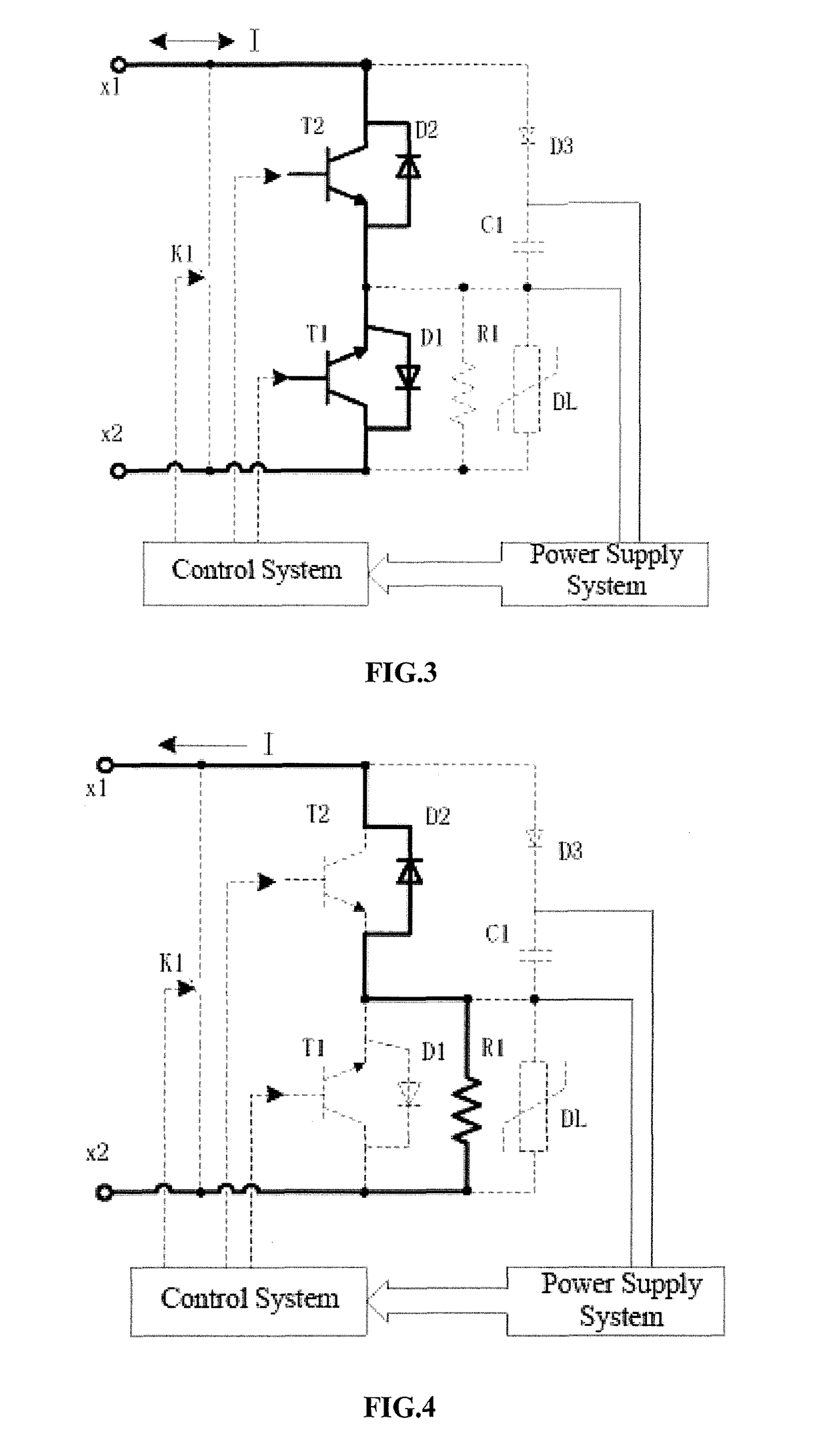
[0052](1) activation forward current charge state: the control system does not send the control signal, the bypass switch K1 is turned off and the switch tube T1 and the switch tube T2 are also turned off; and a forward current flows through the freewheel diode D1, the energy storage capacitor C1 and the freewheel diode D1, such that the energy storage capacitor C1 is charged by the separate diode D3 and the freewheel diode D1, referring to FIG. 2;

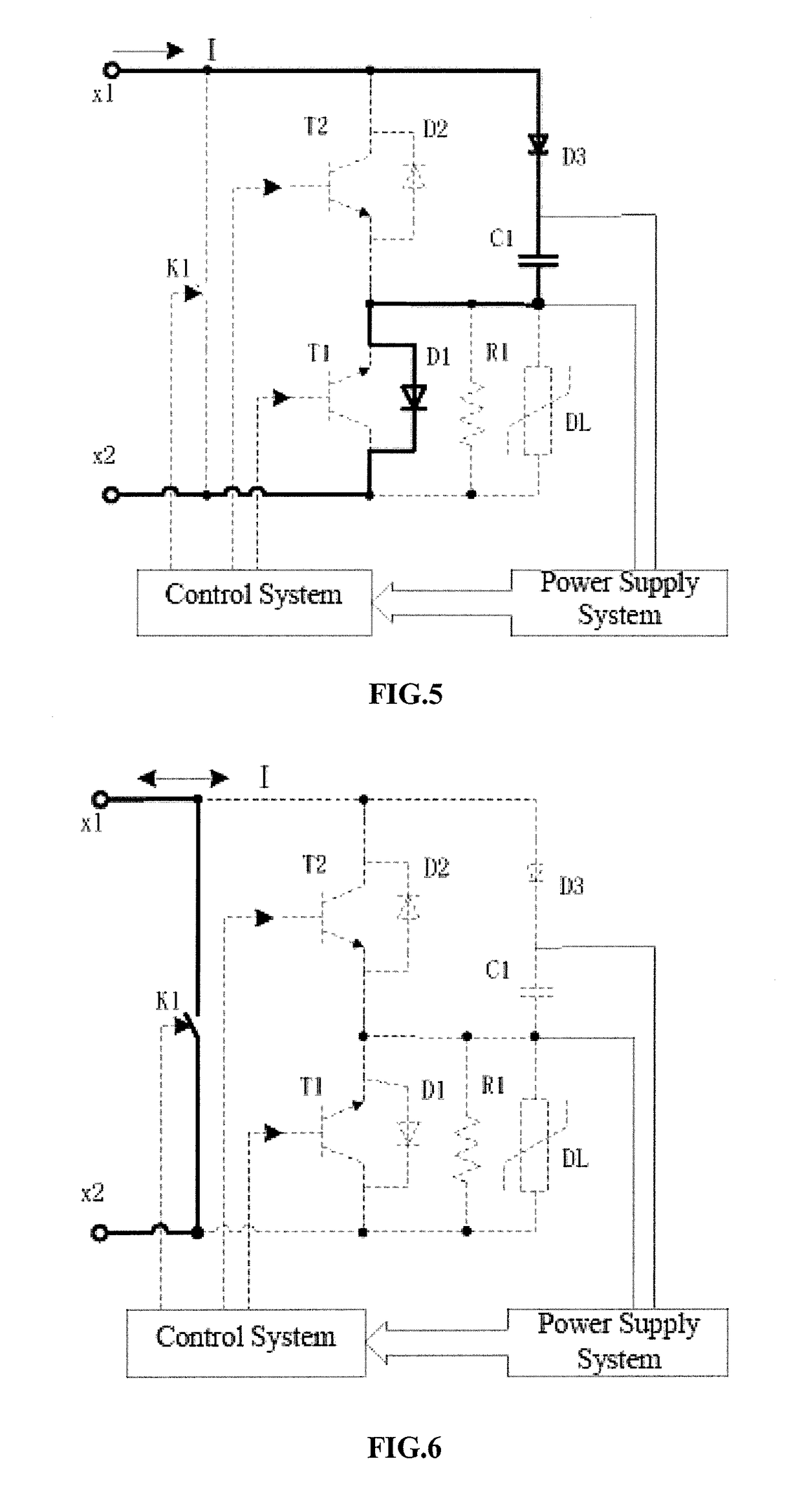
[0053](2) bidirectional current flow state: the control system controls the switch tube T1 and the switch tube T2 to be turned on, such that currents ca...

embodiment 3

[0057]Referring to FIG. 7, a bridge arm damping modular multilevel converter includes an upper bridge arm and a lower bridge arm, the upper bridge atm and the lower bridge arm each include at least one fault current-suppressing damper topology circuit. The fault current-suppressing damper topology circuit is the same as that of embodiment 1, and thus is not described in detail.

[0058]As a preferred embodiment, the upper bridge aim and the lower bridge arm each include at least two half-bridge connected converter module units cascaded with each other. Ua, Ub and Uc respectively represents the network voltage of phase A, B and C. The converter module units in the upper bridge arm are connected in the same direction, and the converter module units in the lower bridge arm are also connected in the same direction. A first leading-out terminal of a first converter module unit in the upper bridge arm is a positive pole P of the modular multilevel converter, and a second leading-out terminal...


PUM


Abstract

Disclosed are a fault current-suppressing damper topology circuit and a control method thereof and a converter. An anode of a separate diode is connected to a positive electrode of a second switch module, a cathode of the separate diode is connected to one end of an energy storage capacitor, and the other end of the energy storage capacitor is connected to a negative electrode of a first switch module; a damping resistor is connected in parallel with an arrester and then with the first switch module; a bypass switch is connected in parallel between a terminal x1 and a terminal x2 of the damper topology circuit; a power supply system acquires energy from the energy storage capacitor and supplies power to a control system; and the control system controls an operating state of the damper topology circuit by controlling the bypass switch, the first switch module and the second switch module. The fault current-suppressing damper topology circuit is applied to voltage source converters. In case of a DC fault, stress resulting from fault currents is reduced by use of a damping resistor, thereby avoiding damages to a device and achieving self-power supply, modularization and independent control. The fault current-suppressing damper topology circuit can be flexibly applied to various types of voltage source converters and has outstanding economic efficiency and technicality.

Description

CROSS-REFERENCE TO RELATED APPLICATION[0001]This application is a 371 application of the international PCT application serial no. PCT / CN2016 / 089946, filed on Jul. 13, 2016, which claims the priority benefit of China application no. 201510379965.0, filed on Jul. 1, 2015. The entirety of each of the abovementioned patent applications is hereby incorporated by reference herein and made a part of this specification.FIELD OF THE INVENTION[0002]The present invention relates to the field of power electronics, and particularly to a damper topology circuit for suppressing a fault current.BACKGROUND OF THE INVENTION[0003]A voltage source converter technique is a novel converter technique based on a turn-off device IGBT (Insulated Gate Bipolar Transistor) technique and a pulse width modulation (PWM) technique. In a low voltage application, a two-level converter composed of IGBTs is widely applied. To address a high-frequency transition of an output voltage of the converter, problems such as hi...

Claims


Application Information

Patent Timeline
Patent Type & Authority Patents(United States)
IPC IPC(8): H02H7/12H03K17/0814H02M7/5387H02M1/32H03K17/081H02M7/483
CPCH02H7/1203H03K17/08116H03K17/08146H02M2007/4835H02M1/32H02M7/5387H02H7/12H02M7/4835H02M7/4837
Inventor XIE, YEYUANZHU, MINGLIANJIANG, TIANGUIBO, CHUANJUNLI, MIN
Owner NR ELECTRIC CO LTD
Why Eureka
Try Eureka