Method of induction weld forming with shear displacement step

a technology of induction weld forming and shear displacement, which is applied in the direction of manufacturing tools, electrical/magnetic/electromagnetic heating, other domestic articles, etc., can solve the problems of requiring extreme care to maintain the degree, requiring substantial plastic flow, and generating upset or flashes. , to achieve the effect of accelerating the ra

Active Publication Date: 2008-03-25
NOETIC TECH INC
View PDF4 Cites 20 Cited by
  • Summary
  • Abstract
  • Description
  • Claims
  • Application Information

AI Technical Summary

Benefits of technology

[0016]A shear-assisted solid state welding method has been invented for bonding metal parts. This welding method exploits the bonding behaviour of hot contacting parts, preferably in a substantially inert environment, to provide a new solid state welding process that introduces shear strain into hot layers of material immediately adjacent the contact interface or faying surfaces to rapidly form a diffusion-like bond. The imposed shear strain greatly accelerates the rate at which the bond forms, relative to typical diffusion bonding under static strain conditions, in a manner somewhat analogous to the effect that stirring has on diffusion rates in liquids. Similar to typical forge or upset welding, this bond forms most readily if the material is in the hot working temperature range. (Hot working temperature is generally understood herein to mean a temperature in the range below melting but sufficiently high so as not to create strain hardening during plastic deformation, where the lower limit of temperature for this characteristic is generally known as the recrystallization temperature.)
[0017]Similar to these existing weld methods, the present invention thus provides a method to bond mating surfaces of metal parts at elevated temperature without melting. Yet unlike with diffusion welding, the bond in accordance with the present invention can be created in the order of seconds or even fractions of a second. Unlike with friction welding, bonding does not require significant (or any) relative sliding between the surfaces to dissipate kinetic energy, thus minimizing or eliminating the need for initial relative velocity between the surfaces, and entailing total displacement distances that are much lower even than those typically associated with induction-assisted friction welding. Unlike with conventional forge welding, the imposed strain in the present method does not tend to produce a large upset or flash. Furthermore, the method of the present invention facilitates almost complete control of flash size, independent of ‘forging force’ requirements for forge or friction welding. This shear-assisted solid state welding method is suitable for joining segments of pipe, such as would be useful in pipelines, well bore drilling and casing operations, and other applications where any or all of its advantages of short weld time, minimal sliding with minimal transverse or shear movement, controlled flash size, and minimally disturbed microstructure are beneficial.

Problems solved by technology

Such single point processes tend to demand more detailed inspection and require greater manufacturing time than ‘global’ joining processes, such as friction welding.
These methods, while apparently capable of rapidly producing high strength solid state welds, thus require extreme care to maintain the degree of metallurgical cleanliness required to promote bonding in both the short period of time the work piece ends remain hot (a few seconds) and without excess flash.
By contrast, conventional forge welds, such as commonly used to produce ERW (electric resistance welded) tubular products, do not require the same degree of cleanliness or time to form a bond, but these benefits come at the expense of requiring substantial plastic flow generating an upset or flash.
Seen in this context, it will be apparent that the weld methods taught by Alford et al, and Moe, while demonstrating that rapid ‘diffusion quality’ welds are metallurgically achievable, are relatively fragile.
Particularly when joining long tubular work pieces, this amount of total rotation or ‘spinning’ still introduces additional complexity and technical limitations for many applications, as for example, at pipeline tie-ins.
This stress state necessarily results in extrusion of a significant volume of hot material, as flash, during the forge process.
In common with other friction welding, this method does not explicitly control the amount of hot working due to shear.

Method used


Image

  • Method of induction weld forming with shear displacement step
  • Method of induction weld forming with shear displacement step
  • Method of induction weld forming with shear displacement step

Examples


Embodiment Construction

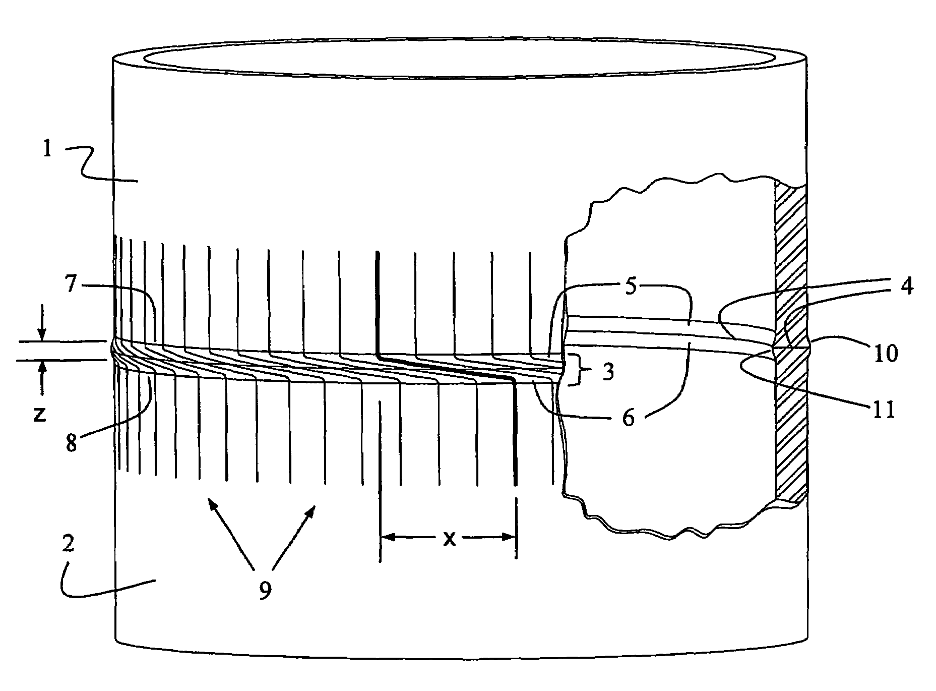
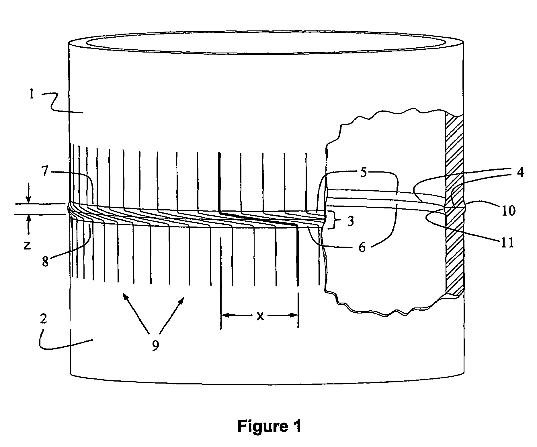
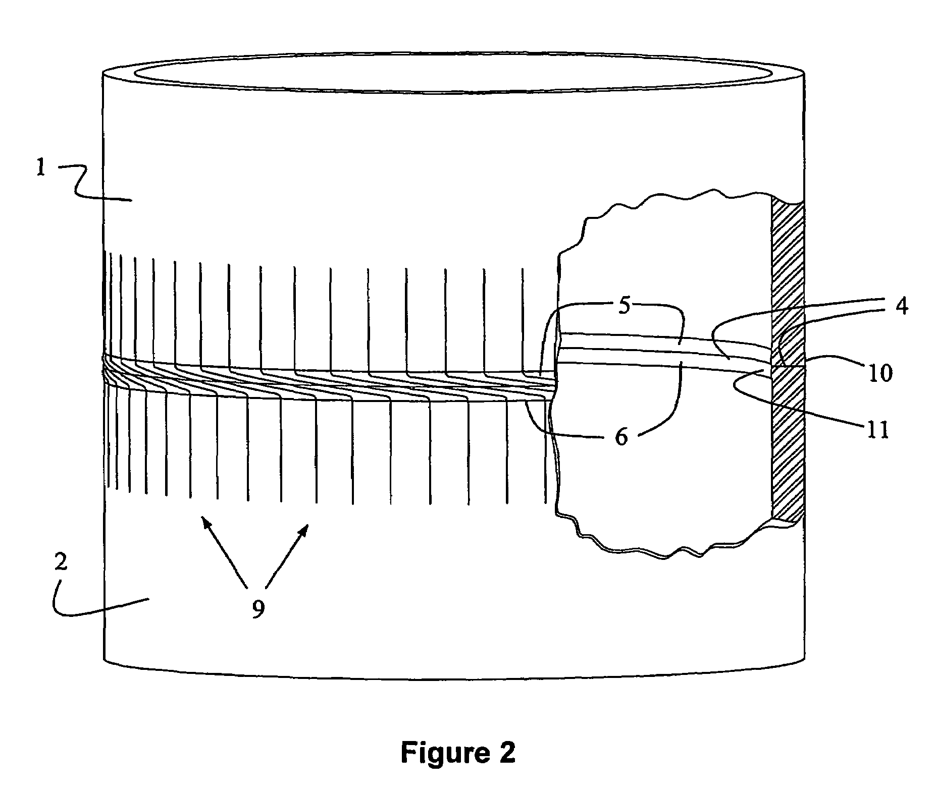
[0071]FIG. 1 illustrates a shear-assisted solid state weld formed by the preferred method of the present invention as it appears in a welded tube or pipe. In FIG. 1, a first metal tubular work piece 1 is coaxially welded to a second metal tubular work piece 2 to create a weld zone 3. The weld zone 3 is bisected by a bond line 4 and is generally defined by first and second heat affected zones, 5 and 6, on the welded ends 7 and 8 of the first and second work pieces respectively.

[0072]According to the preferred method of the present invention, the shearing required to activate the bond in weld zone 3, as described above, is input as uni-directional coaxial relative rotation between work pieces 1 and 2. In such case, axial reference lines scribed along the work pieces 1 and 2, prior to welding, would be distorted and appear as curved lines 9 after welding, which lines show the plastic shear distortion imposed by the welding process. It will be apparent that where line slope is steepest ...


PUM

PropertyMeasurementUnit
circumferenceaaaaaaaaaa
surface velocityaaaaaaaaaa

Abstract

A shear-assisted solid state welding method for joining of metal parts, involves a first step of heating opposing surfaces in a non-passivating environment to a temperature in the hot working temperature range of the metal. A second step involves bringing the opposing surfaces into contact while still in the hot working temperature range, and applying compressive stress sufficient to substantially prevent sliding in response to shear displacement, causing plastic flow in the hot layers. A third step involves imposing relative shear displacement of the metal work pieces without disengaging the opposing surfaces. The shear displacement induces plastic shear strain within the hot layers to progressively induce bonding.

Description

FIELD OF THE INVENTION[0001]The present invention relates to methods of making metal weldments. In particular, the invention relates to a method of rapidly joining metal work pieces having locally heated mating surfaces brought into contact in a non-oxidizing or non-passivating environment by inducing a bond through introduction of shear strain into the material adjacent to the contact interface.BACKGROUND OF THE INVENTION[0002]The task of joining or connecting segments of pipe dominates the construction of wells and pipelines used to produce petroleum and other reservoir fluids. The cost of manufacture and quality control, and the technical attributes of the joins or connections created, provide an ever present motivation for both more efficient and versatile connections. Environmental requirements have served to heighten these demands as most of these are linear systems with little or no redundancy to mitigate the consequence of even a single connection failure.[0003]For such tubu...

Claims


Application Information

Patent Timeline
Patent Type & Authority Patents(United States)
IPC IPC(8): H05B6/10B23K13/02B23K13/06B23K20/02B23K20/12B23K20/14
CPCB23K13/025B23K13/06B23K20/023B23K20/028B23K20/129B23K20/14B23K31/125B23K2201/10B23K2101/10
Inventor SLACK, MAURICE WILLIAMSHUTE, DANIEL MARK
Owner NOETIC TECH INC
Why Eureka
Try Eureka