Method of validating a diagnostic purge valve leak detection test

a purge valve and leak detection technology, applied in the field of vehicle diagnostics, can solve the problems of false failure test, fuel slosh or turbulence in the fuel tank, and achieve the effect of reducing or eliminating false failures and large increase over a short period of tim

Active Publication Date: 2008-04-01
DELPHI TECH IP LTD
View PDF11 Cites 35 Cited by
  • Summary
  • Abstract
  • Description
  • Claims
  • Application Information

AI Technical Summary

Benefits of technology

[0007]One advantage of the present invention is that it provides for the reduction or elimination of false failures on a purge valve leak detection test. In this regard, it has been discovered that a combination of ambient vehicle soak conditions and a driving maneuver sufficient to create fuel “slosh” can create a false test failure. Fuel slosh or turbulence of the fuel within the fuel tank occurs when the vehicle undergoes a series of sudden movements. It has been discovered that if a vehicle is parked when ambient air temperature changes considerably while “soaking” and then the vehicle starts and then moves in a certain manner while the purge valve leak test is running, that a vacuum not due to any purge valve leak (“false vacuum”) is generated in the fuel tank, which then appears to the diagnostic as a “leak”. While this phenomenon is believed to be due to fuel vapor condensation due to the fuel slosh, when the fuel vapor has cooled to a lower temperature than the liquid fuel, it should be understood that the actual mechanism has not been verified, and its presence should not be implied as a requirement of the present invention. The present invention distinguishes between a real leak, which should be reported to the on-board diagnostics, and a false “slosh” induced failure, which should be ignored.
[0008]A method of evaluating the integrity of a leak detection test for a purge valve of a fuel system in a vehicle includes a number of steps. The first step involves determining when vehicle soak conditions meet first predetermined criteria conducive to fuel vapor phase changes in the fuel tank. In one embodiment, the first predetermined criteria includes satisfying a preselected temperature drop.
[0009]The next step involves determining when a vehicle maneuver meets second predetermined criteria indicative of the capability of the maneuver to initiate fuel slosh in the fuel tank thereby establishing a trigger event.
[0010]The next step involves determining, after the trigger event, a maximum slope of fuel tank vacuum increase. The maximum slope value is used to evaluate the effect of the slosh event on the vacuum level.
[0011]The next step involves producing a slope ratio as a function of the maximum vacuum increase slope (calculated in the previous step) and a reference vacuum slope. The reference vacuum slope is a parameter that is unaffected by the fuel slosh. In one embodiment, the reference vacuum slope is a pre-slosh event vacuum slope. In an alternative embodiment, the reference vacuum slope is a predetermined vacuum slope. Slosh induced false vacuum manifests itself by a relatively large increase over a short period of time. This is distinguishable from non fuel slosh induced vacuum increases. The slope ratio compares the post slosh event slope and the reference vacuum slope.
[0012]The final step involves invalidating the purge valve leak detection test when the slope ratio exceeds a predetermined threshold. In one embodiment, the invalidating step may involve discarding the test, or not counting the failure towards a fail count threshold where a diagnostic trouble code (DTC) would have to be set by the on-board diagnostics.

Problems solved by technology

In this regard, it has been discovered that a combination of ambient vehicle soak conditions and a driving maneuver sufficient to create fuel “slosh” can create a false test failure.
Fuel slosh or turbulence of the fuel within the fuel tank occurs when the vehicle undergoes a series of sudden movements.

Method used


Image

  • Method of validating a diagnostic purge valve leak detection test
  • Method of validating a diagnostic purge valve leak detection test
  • Method of validating a diagnostic purge valve leak detection test

Examples


example

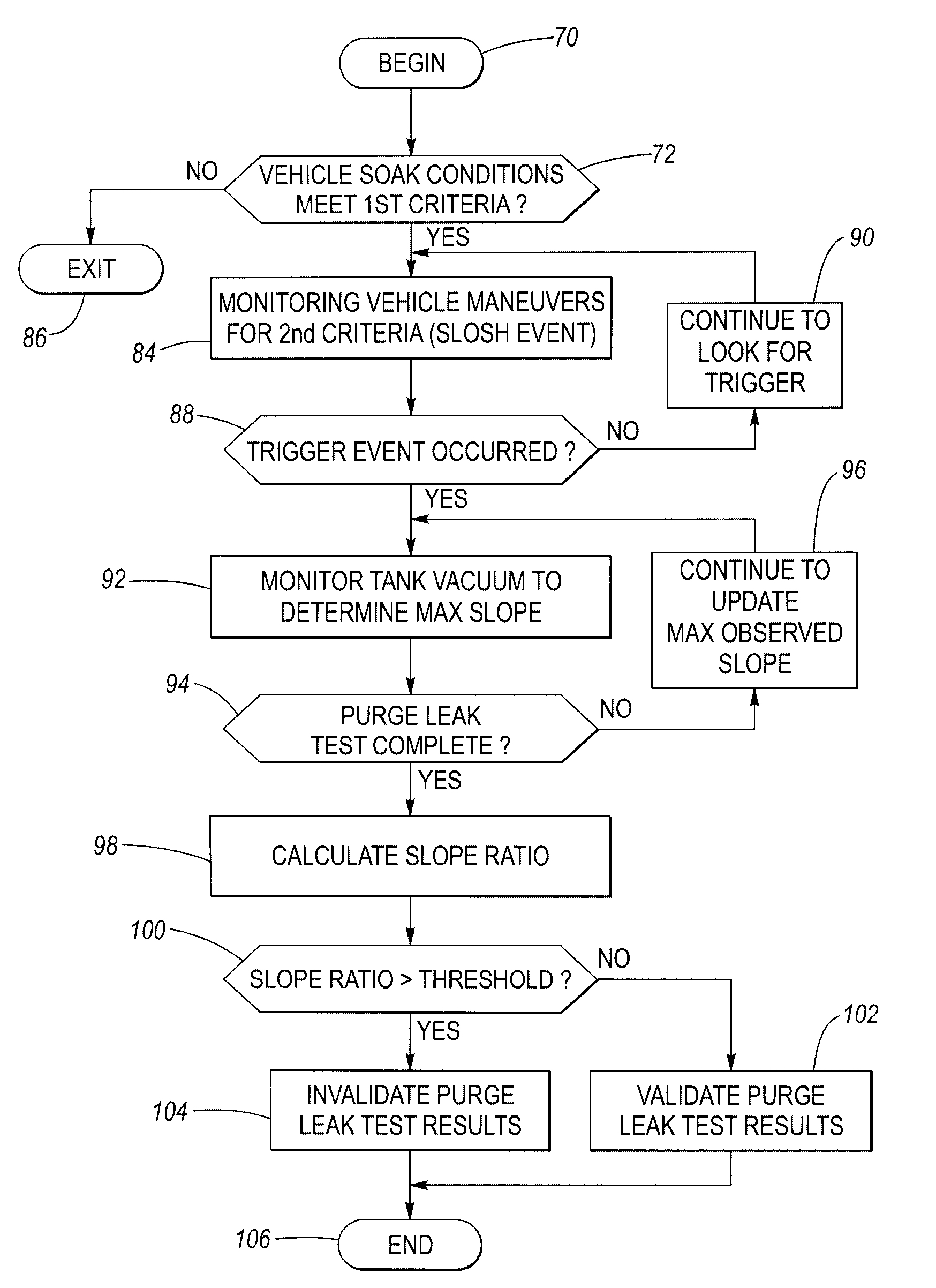
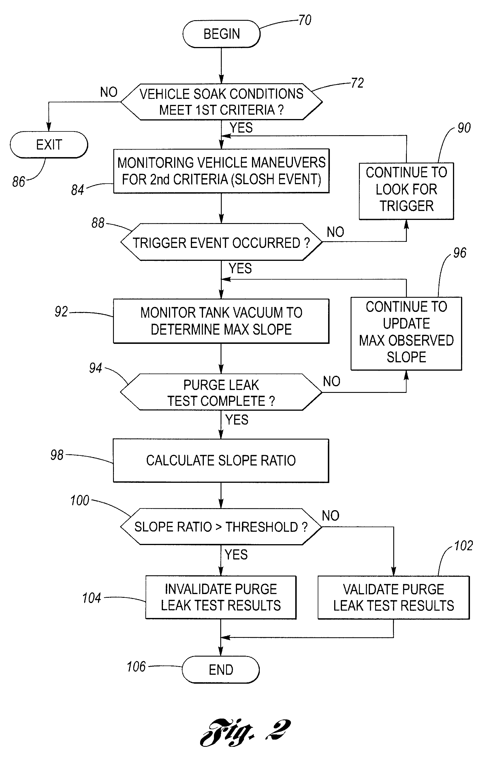
[0030]Consider a vehicle that has “soaked” overnight where the ambient temperature is a relatively constant 65° F. Note, the longer the soak time, the more time that the liquid fuel temperature, the fuel vapor temperature, and the fuel tank skin temperature all have to stabilize to more or less the same temperature (i.e., little temperature differences between them). Under such circumstances, the liquid-to-vapor temperature differential might only be a fraction of a degree C. Such vehicle soak conditions are NOT conducive to fuel vapor phase changes, and therefore, even when driving maneuvers occur that cause fuel slosh, phase change induced vacuum increases do not occur. Accordingly, the results of any purge valve leak detection test that is running will be based on the merits.

[0031]Returning to FIG. 2, decision block 72 is configured to determine when such conditions may have caused partial cooling in the fuel tank and thus significant temperature differences between the fuel vapo...


PUM


Abstract

A system and method for evaluating the integrity of a leak detection test for a purge valve of a fuel system in a vehicle reduces or eliminates false failures. The method is executed on an engine control module (ECM) and is configured to determine when vehicle soak conditions meet first criteria conducive to fuel vapor condensation in the fuel tank. The first criteria include a predetermined temperature drop in ambient air temperature between successive drive cycles. The ECM is further configured to determine when a vehicle maneuver meets second criteria indicative of the capability of the maneuver to initiate fuel slosh in the fuel tank, to thereby establish a trigger event. The ECM is further configured to determine, after the trigger event, the maximum slope of a fuel tank vacuum increase. The ECM is still further configured to produce a slope ratio as a function of the maximum vacuum increase slope and a reference vacuum slope corresponding to a slope that is unaffected by any slosh/condensation events. The ECM is configured to invalidate a purge leak test when the slope ratio exceeds a threshold.

Description

TECHNICAL FIELD[0001]The present invention relates generally to vehicle diagnostics and more particularly to a method of validating a diagnostic purge valve leak detection test.BACKGROUND OF THE INVENTION[0002]Increasing awareness of the effects of vehicle evaporative and exhaust emissions has resulted in regulations at both state and federal levels to control these emissions. In particular, on-board diagnostic regulations (e.g., OBDII) require that certain emission related systems on the vehicle be monitored, and that a vehicle operator be notified if the system is not functioning in a predetermined manner.[0003]One example of an emission related system is a fuel system, which includes a fuel tank for storing fuel. Vapors from the fuel collect within the fuel tank. Occasionally, the fuel tank may develop a leak due to a hole, such as from a sharp object puncturing the fuel tank. Additionally, other components of the fuel system may develop leaks or otherwise begin to operate in a f...

Claims


Application Information

Patent Timeline
Patent Type & Authority Patents(United States)
IPC IPC(8): F02M33/02
CPCF02M25/0809
Inventor MEACHAM, DANIEL R.SHEFFER, TIMOTHY K.OBER, MITCHELL G.SIMPSON, KENNETH M.GALSKOY, CAROL
Owner DELPHI TECH IP LTD
Why Eureka
Try Eureka