End structure of water pipe
a technology of end structure and water pipe, which is applied in the direction of hose connection, coupling, manufacturing tools, etc., can solve the problems of unnecessarily heavy load on the operation of forming a seal structure at the end of the pipe main body, and the complexity of the flange portion, so as to increase the diameter and increase the diameter of the inner pi
- Summary
- Abstract
- Description
- Claims
- Application Information
AI Technical Summary
Benefits of technology
Problems solved by technology
Method used
Image
Examples
first embodiment
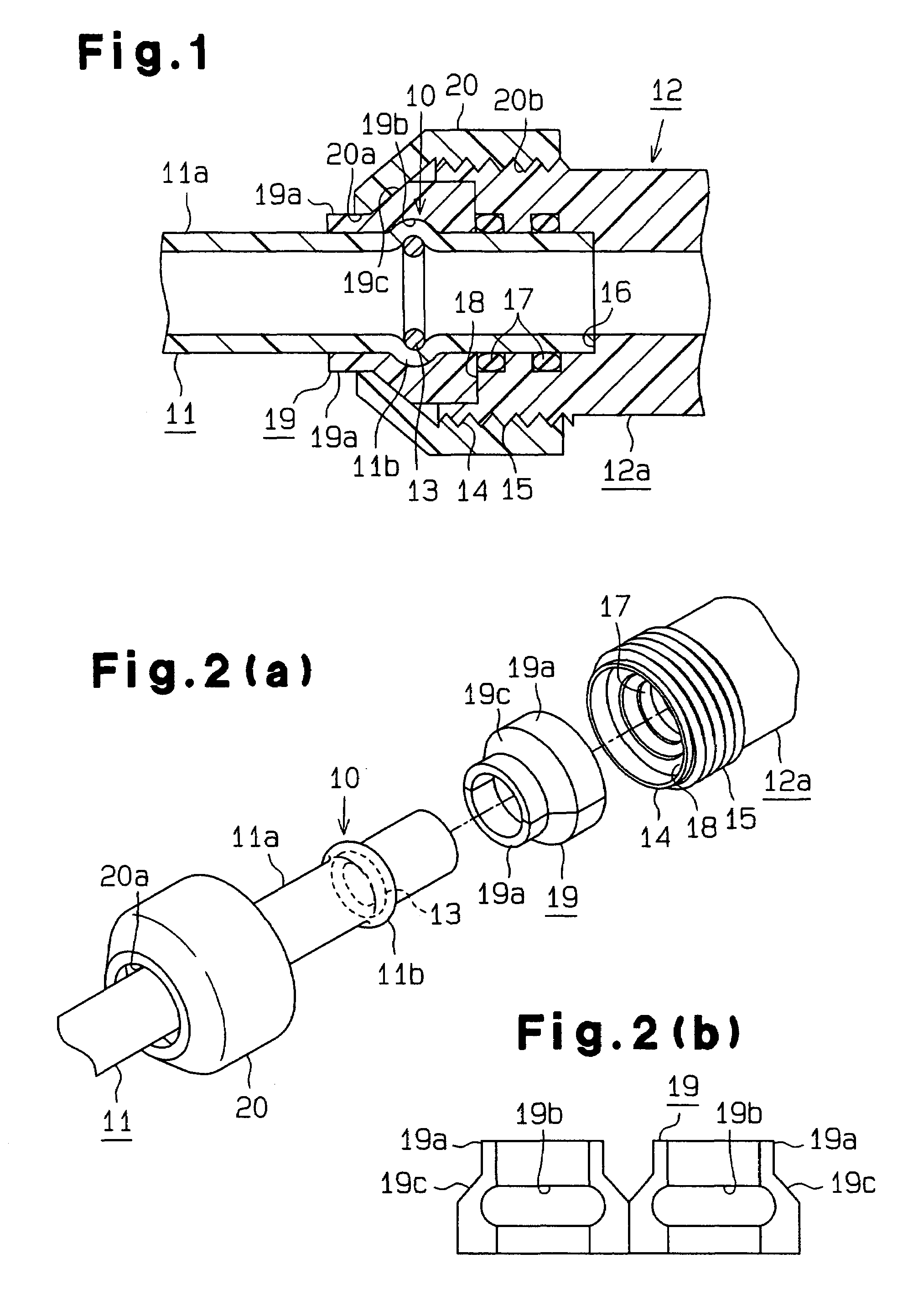
[0076]With reference to FIGS. 1 to 5, description will be given below of a first embodiment that embodies the present invention. The terms “upward”, “downward”, “right”, and “left” in the description below of the present embodiment correspond to the upper, lower, right, and left sides, respectively, of the drawings.
[0077]As shown in FIG. 1, an end structure 10 of a water pipe 11 is formed at the right end of a pipe main body 11a of the water pipe 11 in order to connect, in a lockable manner, the water pipe 11, made of a synthetic resin, to a joint 12 operating as a connector.
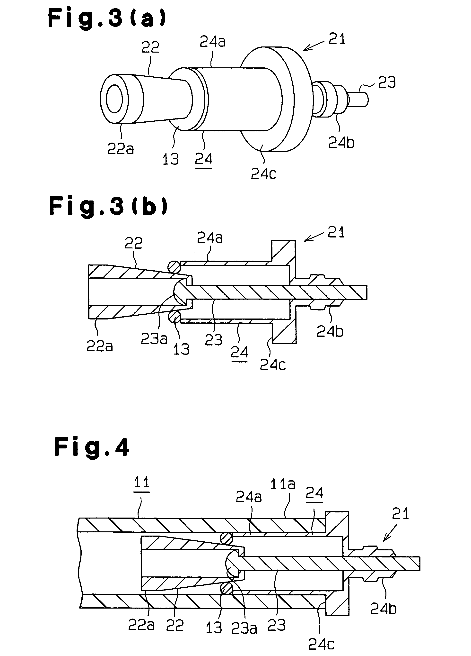
[0078]The end structure 10 comprises a swollen portion 11b provided at the right end of the pipe main body 11a and projected outside by increasing the diameter of a ring piece 13 from the inside of the ring piece 13; the ring piece 13 is inserted into the right end of the pipe main body 11a and operates as an inner piece. The ring member 13 is formed of, for example, copper. The ring member 13 may be formed of m...
second embodiment
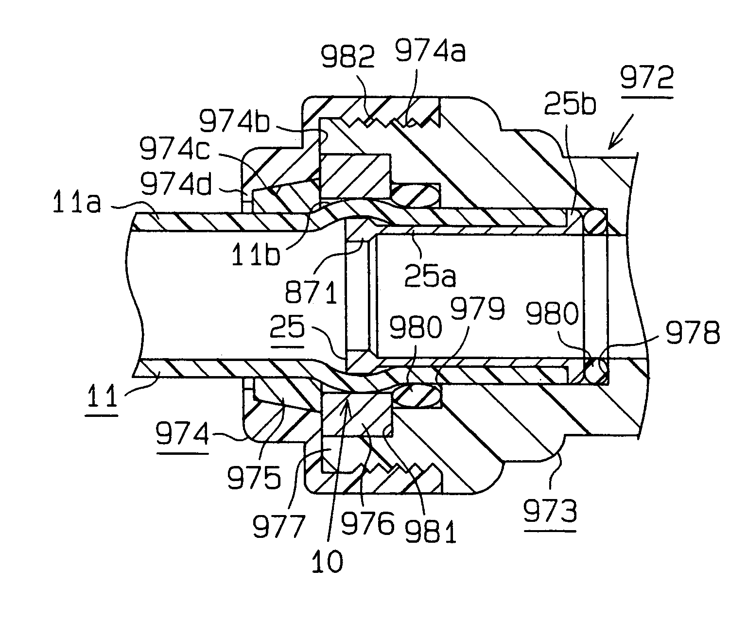
[0109]the present invention will be described below with reference to FIGS. 6 to 8. In the present embodiment, only the configurations of the end structure 10 and joint 12 in the embodiments shown in FIGS. 1 to 5 are changed. Accordingly, the detailed description of similar components is omitted. Also in the present embodiment, the terms “upward”, “downward”, “right”, and “left” in the description below correspond to the upper, lower, right, and left sides, respectively, of the drawings.
[0110]As shown in FIG. 6, in the end structure 10 of the water pipe 11, an inner sleeve 25 made of metal and operating as an inner piece is fitted into the pipe main body 11a between the swollen portion 11b of the pipe main body 11a and the opening in the pipe main body 11a. The inner sleeve 25 may be formed of a synthetic resin. The inner sleeve 25 comprises a cylindrical inner portion 25a and an engagement flange portion 25b formed at the right end of the inner portion 25a so as to project radially...
third embodiment
[0120]the present invention will be described below with reference to FIGS. 9 to 13. In the present embodiment, only the configurations of the end structure 10, ring piece 13, and joint 12 in the embodiments shown in FIGS. 1 to 5 are changed. Accordingly, the detailed description of similar components is omitted. Also in the present embodiment, the terms “upward”, “downward”, “right”, and “left” in the description below correspond to the upper, lower, right, and left sides, respectively, of the drawings.
[0121]As shown in FIG. 9, the end structure 10 of the water pipe 11 comprises the swollen portion 11b formed by increasing the diameter of a cylinder 34 from its inside to swell the end of the pipe main body 11a radially outward; the cylinder 34 is inserted into the right end of the pipe main body 11a and operates as an inner piece. The cylinder 34 is formed of metal and has an outer diameter before enlargement slightly smaller than the inner diameter of the pipe main body Ha (see FI...
PUM
| Property | Measurement | Unit |
|---|---|---|
| diameter | aaaaa | aaaaa |
| outer diameter | aaaaa | aaaaa |
| inner diameter | aaaaa | aaaaa |
Abstract
Description
Claims
Application Information
 - R&D
- Intellectual Property
- Life Sciences
- Materials
- Tech Scout
- Unparalleled Data Quality
- Higher Quality Content
- 60% Fewer Hallucinations
Browse by: Latest US Patents, China's latest patents, Technical Efficacy Thesaurus, Application Domain, Technology Topic, Popular Technical Reports.
© 2025 PatSnap. All rights reserved.Legal|Privacy policy|Modern Slavery Act Transparency Statement|Sitemap|About US| Contact US: help@patsnap.com


