Three-dimensional display using variable focal length micromirror array lens

a micromirror array and variable focal length technology, applied in the direction of mirrors, instruments, mountings, etc., can solve the problems of unsuitable display, limited use of holography for three-dimensional image display, and the method does not generate a three-dimensional image in spa

Active Publication Date: 2008-04-01
STEREO DISPLAY
View PDF87 Cites 8 Cited by
  • Summary
  • Abstract
  • Description
  • Claims
  • Application Information

AI Technical Summary

Benefits of technology

[0010]Objectives of the present invention are to provide a three-dimensional display device that has a simple construction and realistic image representation, to provide a three-dimensional display device and method that utilizes a set of depthwise images, to provide a three-dimensional display device that can display a large range of image depth, to provide three-dimensional display device with three-dimensional images in the various perspectives without moving viewer's position, to provide three-dimensional display device that compensates the aberration of the display device, to provide a three-dimensional display device that has two-dimensional / three-dimensional compatibility, and to provide a three-dimensional display device that has a large variation of the image size.
[0029]The advantages of the present invention are: (1) since the three-dimensional display device actually generates three-dimensional images in space, the device does not suffer from the disadvantage of prior art device using parallax including imaging difficulties due to considerations for arbitrary distribution of the viewer's position, and binocular disparity due to deviations in the distance between the two eyes, vergence, accommodation, and the relative position change of the three-dimensional image due to viewer's movement; (2) The high depth resolution three-dimensional image is provided since the focal length variation speed is very fast; (3) The three-dimensional image can be viewed in the various perspectives without moving user's position; (4) the aberration of the three-dimensional display system can be compensated; (5) the cost for providing three-dimensional image data is inexpensive since the data need only depth information in addition to two-dimensional image information, and thus there is no significant increase in data amount; (6) the device is very simple because there is no macroscopic mechanical displacement for the variable focal length MMAL; (7) the device requires small power consumption since the variable focal length MMAL is actuated by electrostatic force; and (8) the device can be easily converted to a two-dimensional display and vice versa.

Problems solved by technology

This method does not actually generate a three-dimensional image in space.
Therefore, this method has disadvantages that various factors including arbitrary distribution of the viewer's position, binocular disparity due to deviations in the distance between the two eyes, vergence, fatigue accumulation in the eye, accommodation, the relative position change of the three-dimensional image due to viewer's movement, etc., are involved, and such factors must be considered in order to provide a proper three-dimensional display.
Holography has been used for three-dimensional image display very limitedly due to its technical complexity and high manufacturing cost.
Austin's display has a disadvantage that the display is unsuitable for displaying realistic three-dimensional images since the focusing speed of the fluid-filled lens is slow.
The liquid micro-lenses formed on self assembling monolayer may have a strong hysteresis problem, which can cause failure of lenses to return to the original shape when the actuating force is disconnected.
While utilizing a variable focal length lens for three-dimensional display is very promising, the conventional variable focal length lenses have limitation on their performance which includes focusing speed, range of focal length variation, optical focusing efficiency, aperture size, amount of aberration, production cost, etc.

Method used


Image

  • Three-dimensional display using variable focal length micromirror array lens
  • Three-dimensional display using variable focal length micromirror array lens
  • Three-dimensional display using variable focal length micromirror array lens

Examples


Embodiment Construction

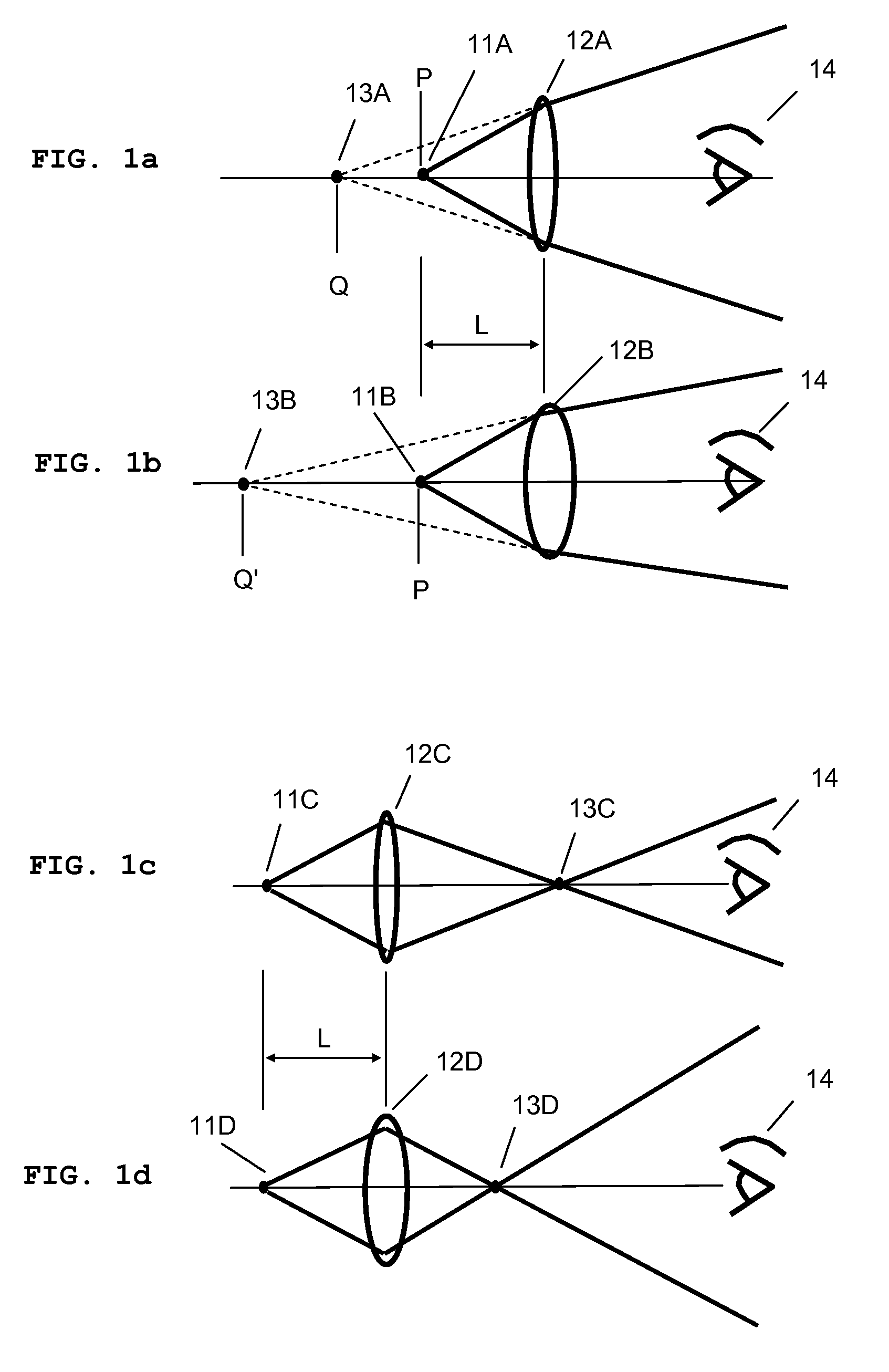
[0043]FIG. 1 illustrates the general principle regarding the distance or depth of an image formed by a lens, and the focal length of the lens. When the light from an object passes through a lens, it converges or diverges depending on the distance L between the object and the lens, and the focal length of the lens. In the description of the present invention, a lens means an optical element that focuses light, and is not confined to a refractive type lens.

[0044]FIG. 1a shows that the light from an object 11A passes through a lens 12A and then diverges at a different angle. FIG. 1b is a similar diagram for a lens 12B having a shorter focal length. The light refracted by the lenses 12A and 12B forms virtual images 13A and 13B, respectively. When a viewer 14 sees the refracted light, the viewer perceives objects 11A and 11B, which is positioned at point P, as existing at points Q and Q′, respectively.

[0045]FIG. 1c shows that the light from an object 11C passes through a lens 12C and the...


PUM


Abstract

A three-dimensional display device includes a two-dimensional display displaying a depthwise image, and a variable focal length micromirror array lens receiving light from the two-dimensional display and forming a corresponding image in the required location in space. Each depthwise image represents a portion of an object or scene having the same image depth, and the two-dimensional display displays one depthwise image at a time. The focal length of the variable focal length micromirror array lens changes according to the depth of the depthwise image being displayed. The variable focal length micromirror array lens has enough speed and focusing depth range for the realistic three-dimensional display.

Description

REFERENCE TO RELATED APPLICATIONS[0001]This application is a continuation-in-part of, and claims priority to U.S. patent application Ser. No. 10 / 778,281 filed Feb. 13, 2004, now U.S. Pat. No. 7,077,523, U.S. patent application Ser. No. 10 / 855,554 filed May 27, 2004, now U.S. Pat. No. 6,970,284, U.S. patent application Ser. No. 10 / 855,715 filed May 27, 2004, now U.S. Pat. No. 7,031,046, U.S. patent application Ser. No. 10 / 855,287 filed May 27, 2004, now U.S. Pat. No. 6,934,072, U.S. patent application Ser. No. 10 / 857,796 filed May 28, 2004, now U.S. Pat. No. 6,934,073, U.S. patent application Ser. No. 10 / 857,714 filed May 28, 2004, now U.S. Pat No. 7,161,729, U.S. patent application Ser. No. 10 / 857,280 filed May 28, 2004, now U.S. Pat. No. 6,999,226, U.S. patent application Ser. No. 10 / 872,241 filed Jun. 18, 2004, U.S. patent application Ser. No. 10 / 893,039 filed Jul. 16, 2004, now U.S. Pat. No. 7,239,438, U.S. patent application Ser. No. 10 / 887,536 filed Jul. 8, 2004, U.S. patent ap...

Claims


Application Information

Patent Timeline
Patent Type & Authority Patents(United States)
IPC IPC(8): G03B21/00G02B26/00G03B21/20G02B27/14G02B5/08
CPCG02B26/0833G02B27/2292G02B30/56
Inventor SEO, CHEONG SOOCHO, GYOUNG ILBAEK, SANG HYUNE
Owner STEREO DISPLAY
Why Eureka
Try Eureka