Retractable syringe assembly designed for one use

a syringe and assembly technology, applied in the field of medical devices, can solve the problems of syringes with extended needles presenting a risk to medical personnel, sanitation employees and others in the disposal chain, and never reaching the market, so as to prevent tampering after retraction, prevent high blowout pressure, and avoid retraction

Inactive Publication Date: 2008-04-01
SHAW CO
View PDF118 Cites 90 Cited by
  • Summary
  • Abstract
  • Description
  • Claims
  • Application Information

AI Technical Summary

Benefits of technology

[0017]The front of the plunger has an opening for a stopper slidingly fitted therein in an interference fit. The stopper is fitted in the opening in an interference fit along a sliding interface oriented in the direction of retraction. The stopper is mostly or fully dislodged by contact with the retraction mechanism at the end of an injection cycle by continued depression of the plunger from a first position at the end of the injection cycle to a second position with the tip of the plunger in contact with the retainer ring. This avoids cumulation of the force on the plunger required to dislodge the stopper from the opening and the force required to dislodge the retainer member from the head of the needle holder and outer body wall. Upon further depression of the plunger from the second position to the retraction position, the frictional holding force on the needle holder is reduced until the retraction force provided by the spring exceeds the remaining holding force and the needle holder and needle connected thereto are ejected into the cavity carrying the dislodged stopper along with them. The dislodging of the stopper and the retainer member alone make the syringe non-reusable. The plunger cannot be removed after retraction because the graspable end cap enters an opening at the back of the barrel when the plunger is depressed to the retraction position to prevent tampering after retraction.
[0018]The retraction cavity of the plunger is preferably vented to prevent a puff of air coming forward at the instant of retraction from blowing a tiny amount of retained fluid from the nose. This condition can occur if the plunger is fully depressed to release the needle holder and dislodge the stopper while the needle is physically restrained from retracting by the septum of a vial which has just been filled with fluid from the syringe. The thumb cap at the rear of the syringe is preferably provided with channels in fluid communication with the interior in cooperation with a closure removably installed in a centrally located opening in the thumb cap. One or more stepped portions of the opening and closure provide seating for the closure. Undercut portions at the side of the closure together with grooves in the interior surface of the plunger wall create passages for air to vent through channels on the thumb cap. This structure prevents air from being trapped by the user's thumb when the thumb cap is pressed to fire the syringe. One or more slots at the back of the barrel around the opening which receives the thumb cap prevent vented air from being trapped by the user's thumb when the plunger is fully depressed.
[0019]The syringe has a high blowout pressure and a low plunger thumb force required to cause retraction. Blowout pressure is the fluid pressure operating on the stopper and retainer ring during an actual injection. High blowout pressure resistance is obtained because the retainer ring is mounted in the most constricted portion of the barrel where the nose begins which significantly reduces the amount of area exposed to fluid pressure. The smaller retainer ring allows the use of a small needle holder such that the opening in the plunger and the stopper can be only a fraction of the cross sectional area of the fluid chamber below the plunger head. The ratio of the greatest cross sectional area of the variable chamber and that of the dislodgeable stopper or the ring member are selected so that the maximum expected thumb force on the plunger during an injection will produce a maximum pressure in the chamber which will generate a blowout force on the stopper and retainer member slightly less than the amount of dislodging force necessary to dislodge the stopper and retainer member during retraction. This ratio should be at least two to one, or more preferably three to one or more, in order to ensure against premature blowout of the stopper or retainer ring.
[0020]In an alternate embodiment, the fewest number of easily made separate parts are used in a retractable syringe. The alternate embodiment has a similar stopper in the head of the plunger and a similar needle holder and spring combination with mating cooperating inwardly facing and outwardly facing interengaged surfaces at the most constricted part of a transition zone where the nose begins. In the alternate embodiment, there is no retainer ring around the head of the needle holder. Instead a tiny ramp is provided at the transition zone or adjacent the transition zone whereby the head of the plunger gently spreads the barrel outwardly while dislodging the stopper thereby reducing the clamping or friction force on the head of the needle holder provided by the wall of the outer body. The holding force is thereby reduced below the retraction force provided by the compressed spring and the needle holder is ejected into the cavity of the plunger carrying the dislodged stopper along with it.
[0021]Manufacture and assembly is facilitated by the fact that the plunger and the outer body can be molded with a non-collapsible core tool that can be pulled out from behind. The parts are simply shaped and do not have hooks and parts with reentrant angles that require collapsible core pin technology. The outer body can be made in one piece and assembled from the rear. The narrowed nose portion provides no lateral space that will permit bunching of the spring and jamming when the retraction assembly is moved forward in the outer body. In fact, the nose serves as a guide to steer the parts into the proper position in one smooth stroke.
[0022]The needle does not have to be installed before the retraction mechanism is put in place because it is readily installed from the front after the needle holder is slidingly lodged in the nose. Significant variations in the holding force on the needle holder and the dislodging force on the stopper due to slight variances in the tolerance of the mating parts is avoided because the longitudinal wall of the outer body has some flexibility. The wall can spread outwardly slightly and the stopper and head of the needle holder can compress slightly radially and expand slightly in the longitudinal direction to avoid significant changes in the holding force caused by small changes in the actual diameters. Consistency in the amount of retraction force is thereby provided and economy is assured.

Problems solved by technology

Used syringes with extended needles present a risk to medical personnel and sanitation employees and others in the disposal chain.
Most of these have never reached the market because of various deficiencies.
Prime among the usual deficiencies of the prior art are problems of complexity, reliability, cost and ease of use.
Cost is a significant factor both in manufacture of the parts and assembly of the device.
Therefore, molded structures within the barrel that require collapsing core pins such as are shown in much of the art are unlikely to be producible at competitive costs.
One of the problems of the prior art of retractable syringes is the sheer number and complexity of parts which must be formed and assembled.
Other problems with the prior art are dependence on flexing or breaking of internal parts by the plunger in order to release the retraction mechanism and use of a diaphragm at the end of the plunger which must be penetrated by a needle holding member and spring.
These structures present serious quality control and assembly problems.
Small broken off pieces can present a risk of hang-ups.
Hooks present difficult holding and control problems, may cause retention of air bubbles upon filling and may be undesirably temperature sensitive.
This leads to difficult assembly problems if the needle must be passed through a small opening.
The extremely sharp tip will catch the edge of a hole and jam the production line.
The rare prior art that employs a front mounted retraction mechanism in a one-piece barrel with a plugged hollow plunger, Tsao U.S. Pat. No. 5,084,018, among other things does not show reduced barrel area to prevent excessive blowout pressure, employs engaging flanges to secure all retraction parts, requires concurrent distortion of internal parts and flanges to effect release, cumulating in excessive force required to retract and requires ventilation holes because of a compartmented barrel.
The prior art has not recognized a retraction mechanism with separable parts that relies entirely on clamping force or friction at a smooth walled reduced diameter transition zone in the barrel with mating lands which are slidably or separably released in response to relatively low thumb pressure while having resistance to premature retraction and high blowout pressure resulting from high pressure produced in the fluid chamber during an injection.

Method used


Image

  • Retractable syringe assembly designed for one use
  • Retractable syringe assembly designed for one use
  • Retractable syringe assembly designed for one use

Examples


Embodiment Construction

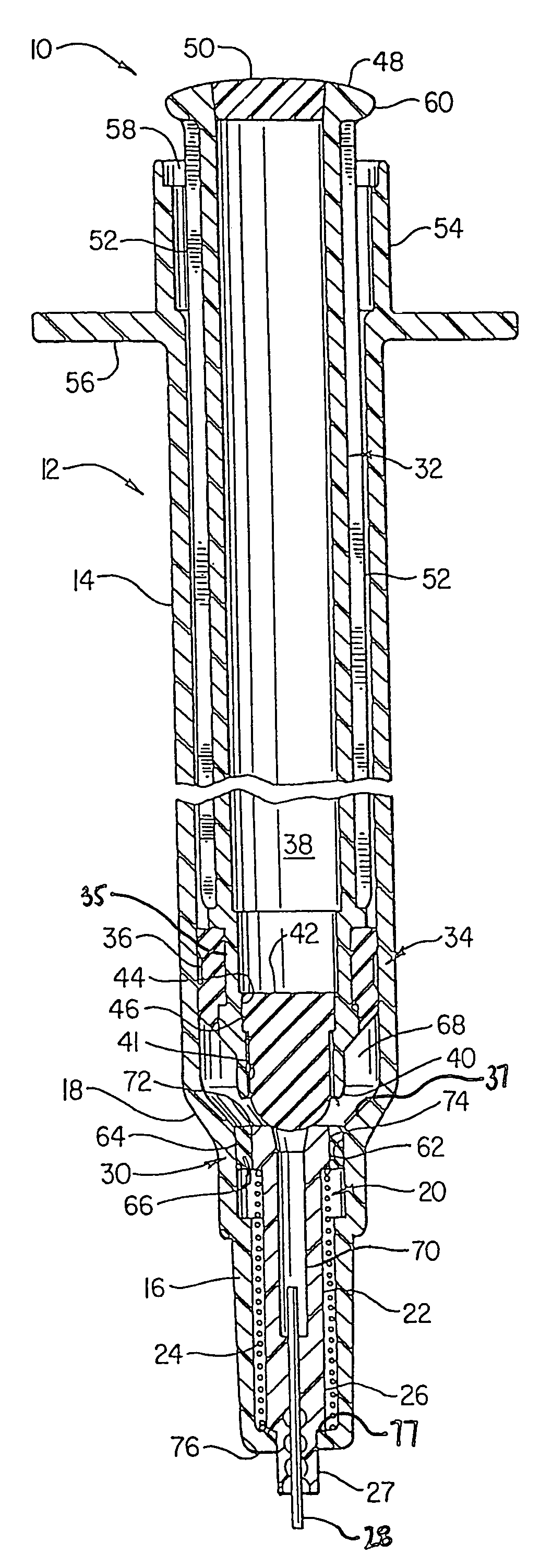
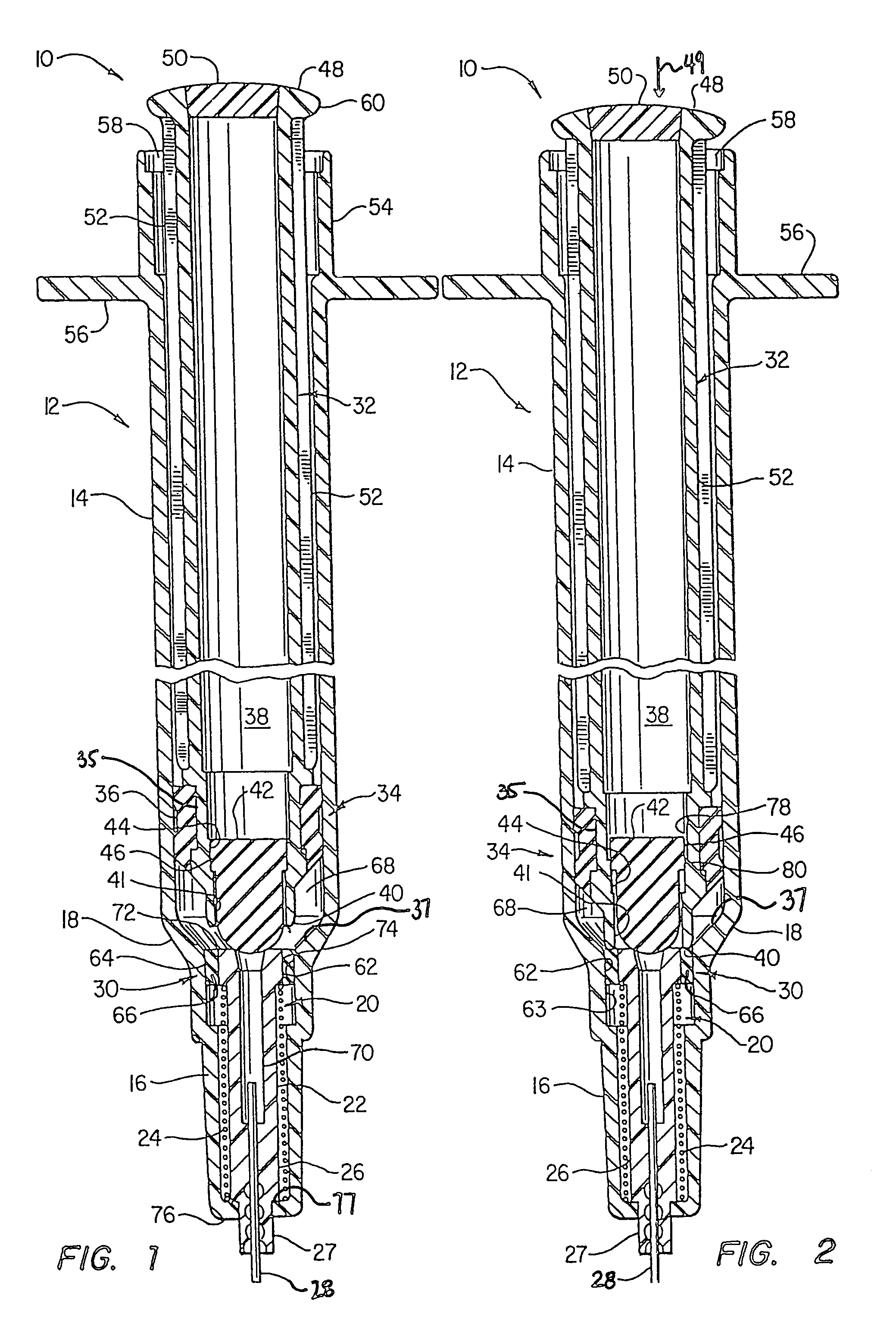
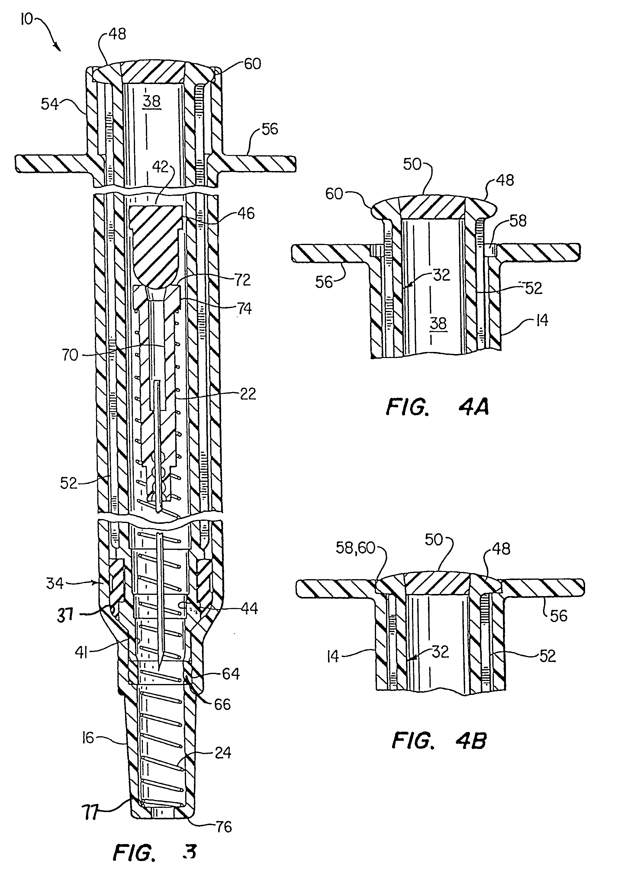
[0040]In the description that follows, like parts will be referred to by the same reference numerals. Parts with a subscript letter are mean to illustrate a minor variation of a part with the same number. The drawings are enlarged significantly in order to show the details of the invention but generally reflect the true scale which is contemplated. The parts as shown are understood to be preferably circular and symmetrical as is conventional for syringes. The drawings reflect a syringe structure typically having a 1 cc to 3 cc injection fluid capacity.

[0041]FIG. 1 shows the structure of the first embodiment generally referred to by reference numeral 10. Syringe 10 has a one piece hollow outer body 12. Body 12 has a longitudinally extending wall comprising an elongated barrel 14 and a nose 16 with a transition zone 18 connecting the barrel and nose. A front mounted retraction mechanism lodged in the nose is generally referred to by the reference numeral 20. It comprises the combinati...


PUM


Abstract

A syringe assembly having a retractable needle, the syringe assembly being rendered unusable after a single injection and having a hollow syringe body, a retraction mechanism with a spring disposed in the front portion of the syringe and an inner head, a continuous retainer member surrounding the inner head, and a bridging portion disposed between the continuous retainer member and the inner head, wherein the bridging portion couples the continuous retainer member and the inner head to form a fluid seal between a fluid passageway and the barrel prior to retraction, and a plunger reciprocally disposed inside the barrel and forming a variable chamber between the plunger and the needle holder prior to and during retraction, wherein the continuous retainer member is releasable from the inner head of the needle holder when the plunger is further depressed inside the barrel following injection.

Description

CROSS REFERENCE TO RELATED APPLICATION[0001]This is a continuation of patent application Ser. No. 08 / 843,050 filed Apr. 25, 1997 entitled “Syringe Plunger Handle Assembly and Barrel, now U.S. Pat. No. 6,090,077, which was a continuation-in-part of patent application Ser. No. 08 / 537,242 filed Sep. 29, 1995 entitled “Tamperproof Retractable Syringe”, now U.S. Pat. No. 5,632,733, which in turn was a continuation-in-part of patent application Ser. No. 08 / 438,954 filed May 11, 1995, now U.S. Pat. No. 5,578,011, all by the same inventors, for which benefit of 35 U.S.C. § 120 is claimed.FIELD OF THE INVENTION[0002]This invention relates to a medical device, and more particularly to a retractable syringe and components suitable for mass production and assembly having a low triggering force and high blowout pressure which is nonreusable after one use.BACKGROUND OF THE ART[0003]A major cause to the spread of AIDS in the general population is the presence of IV drug users who share and reuse h...

Claims


Application Information

Patent Timeline
Patent Type & Authority Patents(United States)
IPC IPC(8): A61M5/00A61M5/32A61M5/178A61M5/50
CPCA61M5/3234A61M5/502A61M5/508A61M2005/3235A61M2005/3236A61M2005/3239
Inventor SHAW, THOMAS J.
Owner SHAW CO
Why Eureka
Try Eureka